
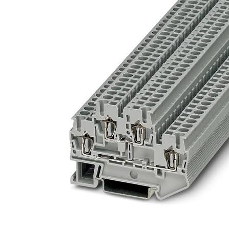
Screw vs Spring vs Push-in Terminal Blocks: How to Choose
Screw vs Spring vs Push-in Terminal Blocks: How to Choose
By the Antong Engineering Team · Reviewed August 2026 · 12 min read
Every panel builder eventually hits the same fork in the road: screw, spring, or push-in? The three connection technologies all do the same basic job — clamp a copper conductor against a current bar — but they trade off wiring speed, vibration resistance, maintenance, and cost in very different ways. Choose wrong and the symptom shows up later: a screw block found loose during a vibration inspection, a push-in block specced for unferruled flexible wire it cannot grip, or a spring block bought at a premium for a static cabinet that never needed it.
After 35+ years of manufacturing terminal blocks and shipping them to 70+ countries, we field this comparison question almost daily from panel builders and OEM engineers. This guide walks through how each technology actually works, how they compare on the metrics that matter, and how to match the right one to your application.
Quick answer: Screw clamps are the proven workhorse — highest flexibility, lowest cost, universal acceptance, but slower to wire and able to loosen under vibration. Spring-cage uses a preloaded stainless steel spring for constant pressure, making it vibration-proof and maintenance-free at a slightly higher price. Push-in is the fastest way to terminate solid or ferruled conductors, ideal for high-volume panel shops, but it needs prepared wires and costs the most per piece. In short: screw for flexibility and cost, spring for vibration and zero maintenance, push-in for speed and repeatability.
In this guide
The Three Connection Technologies at a Glance
All three technologies are evaluated to the same international product standard — IEC 60947-7-1, Low-voltage switchgear and controlgear — Part 7-1: Terminal blocks for copper conductors — which defines the rated cross-section, rated current (proven by temperature-rise testing), and mechanical requirements every block must meet. What differs is the clamping unit, the part that turns a strip of brass and a piece of wire into a reliable electrical joint.
| Technology | Clamping principle | Tool needed | Best-known strength |
|---|---|---|---|
| Screw clamp | Screw-driven yoke presses the wire against the brass current bar | Screwdriver | Flexibility and high clamping force |
| Spring-cage | Preloaded stainless-steel spring holds the wire under constant pressure | Small lever tool | Vibration resistance, maintenance-free |
| Push-in | Spring leg parts for a solid/ferruled wire; self-clamps on insertion | None (tool only to release) | Fastest wiring for prepared conductors |
The table above is the short version. The next section explains exactly what happens inside each one, because the mechanism is what determines the failure modes you will (or will not) have to manage.
Mechanism Deep Dive
How a screw clamp holds the wire
A screw terminal block converts rotational tightening force into clamping force. Turning the screw drives a yoke or saddle (in better designs, a captive pressure plate) down onto the conductor, forcing it against the brass current bar. The joint is held by the clamping force of the screw, not by incidental contact.
There are two common geometries:
Direct clamp — the screw tip or a small washer bears directly on the wire. Simple and cheap, but the screw can bite into fine strands if over-torqued.
Saddle (yoke) clamp — a shaped metal saddle distributes the screw's force over a wider area of the conductor. This protects fine-stranded wire and gives a more repeatable contact, which is why saddle clamps dominate in quality feed-through blocks.
When torqued to the datasheet value, a screw clamp produces a gas-tight, low-resistance contact capable of carrying the block's full rated current. The catch: that contact force depends on staying torqued, which is exactly where screw technology can fall short over time.
How a spring-cage holds the wire
A spring-cage terminal block replaces the screw with a preloaded stainless-steel spring. You lever the spring open with a small operating tool (usually a flat screwdriver), insert the conductor into the cage, and withdraw the tool. The spring snaps shut and applies a near-constant contact force for the life of the connection.
The key word is constant. The spring is a stored-energy device: as the conductor settles, cold-flows, or expands and contracts with temperature, the spring takes up the slack automatically. There is no torque to set, and in normal service no re-tightening schedule.
How push-in holds the wire
A push-in terminal block is spring technology with the tool step removed for prepared conductors. Inside, a spring leg is angled so that a solid conductor — or a flexible conductor fitted with a ferrule — can simply be pushed in by hand. The spring leg deflects open on insertion and then bites down to lock the wire.
To release the wire (or to insert unferruled flexible wire, which would otherwise splay against the spring leg), you press the integrated operating button with a screwdriver to open the spring. This is the critical limitation to design around: push-in's speed advantage assumes your wires arrive ferruled or solid.
Performance Comparison
This is where the three technologies separate in ways that show up in the field — and in your rework budget.
Wiring time per connection
Wiring speed is the most visible difference on a production line. Typical per-termination times reported across manufacturer application notes are:
| Technology | Typical time per wire (prepared conductor) | Why |
|---|---|---|
| Screw | ~5–8 seconds | Strip, insert, then torque (and verify) the screw |
| Spring-cage | ~3–5 seconds | Strip, tool-open, insert, release |
| Push-in | ~1–2 seconds | Strip, then push straight in — no tool |
Treat these as relative benchmarks rather than absolute guarantees: actual time depends on wire size, ferrule quality, tooling, and operator skill. The direction of the difference, however, is consistent — push-in is roughly two to four times faster than screw termination for prepared conductors, and that compounds across a panel with hundreds or thousands of connection points.
Vibration resistance (IEC 60068-2)
Vibration is where spring-based technologies earn their premium. The IEC 60068-2 series defines the environmental test methods — sinusoidal vibration (60068-2-6), shock (60068-2-27), and random vibration (60068-2-64) — used to validate equipment in service.
Screw clamps rely on friction and preload. Sustained vibration, thermal cycling, and conductor cold-flow can cause the screw to relax, increasing contact resistance and generating heat. The joint does not fail instantly — it degrades — which is why inspection schedules and re-torquing exist.
Spring-cage and push-in maintain contact force through a spring that follows the conductor. They self-compensate for vibration, shock, and thermal expansion, which is why they are the default choice for railway, marine, wind, and heavy-machinery applications.
The practical test we suggest to customers: if a screw block on the same machine has ever been found loose during a routine inspection, that circuit is a candidate for spring or push-in technology.
Clamping force and contact resistance over thermal cycles
Every connection cycles through load heating and ambient cooling. Under thermal cycling:
Screw connections can see their contact force decline as the conductor settles and the joint relaxes. A correctly torqued, properly engineered screw clamp still performs well, but it is the technology most sensitive to installation discipline over its service life.
Spring connections keep force essentially flat. The spring compensates for conductor settlement, so contact resistance stays low and stable — a key reason spring and push-in blocks are considered maintenance-free in normal service.
Maintenance: re-torque vs maintenance-free
Screw — recommended practice is to torque to spec at installation and re-check after initial thermal cycling (and periodically in high-vibration duty).
Spring-cage / push-in — no torque to set and no re-tightening schedule. The connection is inherently maintenance-free, which matters where re-opening a panel is expensive or access is poor.
Cost Considerations
Upfront unit cost
As a rule, screw is the lowest-cost, spring-cage sits in the middle, and push-in is the highest piece price for an equivalent current rating and pitch. The difference per piece is small; the difference per panel is not, because terminal blocks are bought by the hundred or thousand.
Total installed cost
Unit price is only part of the picture. Total installed cost includes wiring labor, and labor usually dominates:
A push-in block that costs a few cents more per pole can pay for itself many times over on a high-volume line where each termination saves 4–6 seconds.
A screw block's savings disappear if vibration forces a re-torque program, a service call, or a warranty claim.
The honest calculation is: (unit price × quantity) + (labor rate × wiring time) + (lifetime maintenance and rework cost). For a static, low-volume cabinet, screw often wins on that equation. For a 1,000-point production panel or a vibrating machine, spring or push-in usually wins.
Tooling requirements
Screw — a standard screwdriver (ideally a torque screwdriver for critical or high-current connections).
Spring-cage — a small flat-blade lever tool, plus ferrules recommended for fine flexible wire.
Push-in — no tool to insert prepared conductors, but ferrules become mandatory for flexible wire, and a ferrule crimp tool becomes part of your upstream process cost.
The tooling difference is really a process difference: push-in shifts cost from the panel shop floor back to wire preparation.
Application Matching Guide
Choose screw when…
High current and large cross-sections are involved — screw clamps span the widest range and pair naturally with heavy conductors.
Field wiring demands flexibility: installers may terminate solid, stranded, or flexible wire with whatever is on hand.
Cost is the dominant constraint and the environment is static or low-vibration.
Your team is unfamiliar with spring technology — screw termination is understood everywhere and needs no retraining.
Antong example: our feed-through terminal blocks family is the classic screw-clamp workhorse, covering U-type, V-type and H-type multi-pole blocks in PA66, PP, PE, PVC and bakelite housings, with VDE and NF certified variants for regulated markets.
Choose spring-cage when…
Vibration or shock is part of the environment — railway, marine, wind turbines, mobile machinery, presses.
The installation must be maintenance-free and access for re-torquing is difficult or impossible.
You want operator-independent terminations that do not depend on how hard someone turned a screw.
Choose push-in when…
You run a high-volume panel shop or series production where seconds per connection compound into hours per panel.
The wiring is PLC/IO, sensor/actuator, or other ferruled or solid conductors — the kind of repetitive, prepared wiring where push-in is fastest.
Repeatability and speed matter more than the small per-piece premium.
If you are still unsure
The same three-parameter logic that runs through our full terminal block types guide applies here: vibration → spring; speed + ferrules → push-in; flexibility and cost → screw. The comparison table below condenses it into one view.
Comparison Table
This original table summarizes the three technologies side by side. Current figures are orientation ranges — the binding values are always on the specific product datasheet.
| Criterion | Screw clamp | Spring-cage | Push-in |
|---|---|---|---|
| Wiring speed | Medium (~5–8 s) | Fast (~3–5 s) | Fastest (~1–2 s, prepared wire) |
| Typical current range | Broad — from signal up to high-current blocks | Up to ~35 mm² class | Up to ~35 mm² class (usually 16–25 mm²) |
| Conductor types | Solid, stranded, flexible — with or without ferrules | Solid, stranded, flexible (ferrules recommended for flex) | Solid or ferruled flexible only for tool-free insertion |
| Vibration resistance | Moderate — can loosen; re-torque advised | High — self-compensating | High — self-compensating |
| Maintenance | Re-torque after settling / periodic in vibration | Maintenance-free | Maintenance-free |
| Upfront cost | Lowest | Medium | Highest |
| Tooling | Screwdriver (torque screwdriver ideal) | Lever tool | None to insert; ferrule crimp tool for flex |
| Best use | General industry, power distribution, field wiring, cost-sensitive | Railway, marine, wind, high vibration, hard-to-access | High-volume panel shops, PLC/IO wiring, ferruled conductors |
FAQ: Frequently Asked Questions
Are push-in terminal blocks reliable for high current?
Push-in blocks are highly reliable within their rated range — but that range tops out around the 16–35 mm² class in typical product lines. They are not the right tool for genuinely high-current feeders. For large cross-sections, use screw clamps (which span the widest range) or, above roughly 35–50 mm², bolt/stud terminal blocks with a cable lug torqued onto the busbar. Match the technology to the cross-section, and always design from the datasheet's rated current (proven by temperature-rise testing to IEC 60947-7-1) rather than intuition.
Do spring terminal blocks need torque checks?
No — that is the point. Spring-cage and push-in blocks have no torque setting and, in normal service, no re-tightening schedule. The stainless-steel spring maintains near-constant contact force and self-compensates for conductor settlement and thermal cycling. The only "checks" are the same visual inspections any connection deserves: correct wire depth, no splayed strands, and a properly crimped ferrule where one is used.
Can I use push-in terminals with stranded wire without ferrules?
Not reliably. Unferruled flexible (fine-stranded) wire tends to splay against the spring leg, so you must open the spring with the operating button and insert it manually — which erases push-in's tool-free speed advantage and risks a poor connection if strands are not fully contained. For flexible wire, fit a ferrule first; then the conductor behaves like a solid wire and inserts tool-free. For solid conductors, no ferrule is needed. This is the single most common selection mistake we see with push-in blocks.
Next Steps: Choosing the Right Terminal Block
The technology decision is the hard part; matching an exact series, pitch, current rating, and certification to your bill of materials is the next step. Here is how Antong can help:
Browse the range — explore the complete all products catalog, including screw-clamp feed-through terminal blocks and panel-mount unipolar terminal blocks.
Request the full catalog — get dimensional drawings, rated currents, material data, and certification details for every series.
Order samples — validate clamping force, wire entry, and termination time on your actual conductors before committing to volume.
Talk to engineering — send your current, wire type, vibration profile, volume, and target-market certifications, and our engineers will recommend a specific series and technology.
Antong has manufactured terminal blocks since 1989, operating a 55,000 m² facility with ISO 9001 quality management and shipping to 70+ countries. We support OEM/ODM branding, custom pole counts, and material options — and we are happy to benchmark the three technologies against your actual production wiring time so you can put a number on the labor savings.
References & standards
IEC 60947-7-1, Low-voltage switchgear and controlgear — Part 7-1: Ancillary equipment — Terminal blocks for copper conductors — IEC Webstore
IEC 60068-2, Environmental testing — Part 2: Tests (vibration, shock, temperature) — IEC Webstore
WAGO, Material Specifications (PA66/PBT/PC; CTI, RTI, UL 94) — wago.com
Antong product documentation — safetypass.com
Technical content prepared by the Antong Engineering Team from 35+ years of terminal block manufacturing experience. Wiring-time and current-range figures are orientation benchmarks; rated values must always be confirmed against the specific product datasheet before design release.