
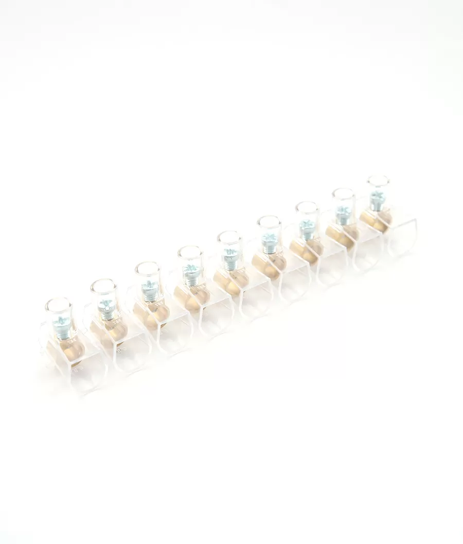
Screw Terminal Blocks: How They Work and How to Select Them
Antong product selection reference · Updated 2 November 2026
A screw terminal block uses a threaded fastener to generate the pressure that holds a conductor against a conductive contact. The housing keeps neighboring circuits separated and supports the assembly. Reliable operation depends on the whole connection: wire preparation, contact geometry, tightening method and the selected product rating.
“Screw terminal” describes how the clamp is operated. It does not tell you whether the screw presses directly on the wire, acts through a protection piece, or moves a separate clamping cage.
Follow the current path and the force path
In a simple through connection, current travels from conductor A into the conductive insert and out through conductor B. The screw supplies clamping force; it is not necessarily the principal part carrying current between the two wires.
In a direct-pressure design, the screw acts on the conductor in the contact opening. In a protected design, an intermediate plate or protection element helps transfer pressure to the conductor. Cage or yoke designs move another clamping part. The correct preparation procedure depends on which construction is actually supplied.
| Path | What to identify |
|---|---|
| Electrical path | Wire A → conductive contact or bar → wire B |
| Mechanical force path | Screw thread → pressure surface or clamp → conductor against contact |
| Insulation boundary | Housing and spacing between adjacent conductive assemblies |
This is a functional illustration, not a sectional drawing of every Antong model. Request a model drawing when the internal contact arrangement affects conductor approval.
Antong examples: the same mechanism, different duties
| Catalogue model | Wire Range | Amp | Volt | L / mm | W / mm | H / mm |
|---|---|---|---|---|---|---|
| SP004-01 | 2.5-4.0mm² | 3A | 380V | 93.5 | 13.0 | 10.8 |
| SP014-01 | 2×6mm² | 32A | 450V | 20.0 | 12.0 | 22.5 |
SP004 is a compact PE terminal strip. SP014/SP015 is a separate PC terminal family; SP014-01 lists a 2 × 6 mm² configuration and 32 A at 450 V. The “2 ×” catalogue entry must be read with the actual connection drawing. It is not blanket permission to put two arbitrary conductors under one screw.
The SP002 wire-protection range uses nickel-plated brass contacts and a stainless-steel protection spring. It remains screw-operated: the presence of a spring does not turn it into a push-in terminal. The SP037/UKK distribution range uses separate input and output positions, whose conductor capacities must be checked individually.
Prepare the conductor for the approved clamp
- Confirm conductor material, cross-section and construction. A matching mm² value alone does not prove approval for every solid or flexible wire.
- Use the specified strip length. Keep insulation out of the electrical contact area and avoid exposed conductive length beyond the intended entry.
- Use a ferrule only where the connection instructions permit it, with the correct size, barrel length and crimp. A plastic collar can interfere with full insertion.
- Check the permitted number of conductors per terminal point. Two separate terminal points are not equivalent to two wires sharing one clamp.
WAGO’s ferrule guidance illustrates why ferrule length, cross-section and collar geometry need separate checks. Its instructions concern its own products; they do not supply missing Antong installation values.
Torque: use a product value, not a thread-size guess
A catalogue entry such as M2.5 or M4.0 identifies the screw thread. It does not specify an installation torque. The torque must suit the screw, contact, housing, conductor and approved configuration together.
Obtain the value and permitted range from the product installation data. Select the specified driver type and a suitable controlled-torque tool. Inadequate pressure can leave a poor connection; excessive tightening can damage the thread, clamp or conductor. Neither risk is solved by simply turning the screw harder.
If a replacement terminal arrives without an installation torque, request the missing instruction before commissioning it. Record the value with the assembly instructions so operators do not use a remembered setting from another product.
Inspection and maintenance
With the circuit safely isolated and verified de-energized, check full insertion, stray strands, damaged insulation, loose mounting and evidence of heating. Follow the equipment and terminal instructions for any prescribed inspection or re-tightening procedure.
Do not impose an automatic re-tightening schedule on every screw design or assume every spring design needs no inspection. Maintenance depends on the documented construction and service conditions. A discolored or damaged joint needs investigation of load, preparation and connection integrity, rather than repeated tightening alone.
Choose the right screw terminal for the job
Screw terminals are useful when the assembly process can control conductor preparation and tightening, and when the chosen model provides the required access and ratings. For repeated harness removal, compare pluggable terminal strips; for another clamping approach, compare screw, spring-cage and push-in technologies.
Send Antong the model or dimensional drawing, actual conductor and end treatment, circuit current and voltage, enclosure temperature, mounting arrangement and quantity. Those details allow a meaningful comparison between a small fixed strip and a distribution block instead of treating all screw products as interchangeable.
Product references
Model values above come from the linked Antong product pages. Confirm the ordered version and installation instructions before final selection.