
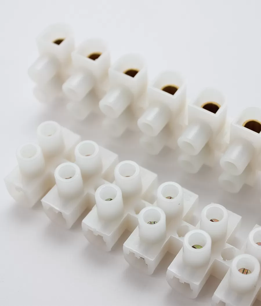
Terminal Block Types: The Complete Guide
Terminal Block Types: The Complete Guide (With Pictures)
By the Antong Engineering Team · Reviewed August 2026 · 18 min read
If you have ever stared at a parts catalog and wondered whether you need a screw, spring, or push-in terminal block — or what actually separates a DIN rail block from a barrier strip — this guide is for you.
After 35+ years of manufacturing terminal blocks for customers in 70+ countries, we have seen almost every selection mistake there is: a screw block chosen for a high-vibration machine that loosened every quarter; a push-in block specced for unferruled flexible wire it could never grip; a barrier strip imported into a panel built around a 35 mm DIN rail. Most of these problems are solved in the first five minutes of choosing the right type.
This guide explains all nine terminal block types you will actually encounter, how each connection technology works, where it does (and does not) belong, and how to choose between them. A comparison table and a step-by-step selection framework are at the end.
Quick answer: The nine main types of terminal blocks are screw-type, spring-cage, push-in, bolt-type (stud), barrier, DIN rail, PCB-mount, pluggable, and specialty (fused, disconnect, multi-level, sensor/actuator). Screw blocks are the universal default; spring and push-in win on speed and vibration; bolt and barrier blocks handle high current; PCB and pluggable types serve board-level and modular wiring. Read on for the detail.
In this guide
What Is a Terminal Block?
A terminal block (also called a terminal connector or connection terminal) is an insulated, modular component that joins two or more copper conductors securely and inspectably — without soldering, wire nuts, or twisting wires together.
Under IEC 60947-7-1, the international product standard for terminal blocks, it is formally defined as "an insulating part carrying one or more mutually insulated terminal assemblies and intended to be fixed to a support." The 2009 third edition (ED3) covers blocks for round copper conductors from 0.2 mm² to 300 mm² (AWG 24 to 600 kcmil) in circuits up to 1,000 V AC or 1,500 V DC; the current 2025 fourth edition (ED4) extends the lower end down to 0.05 mm² (30 AWG) while keeping the same 300 mm²/600 kcmil upper limit and voltage ceiling [IEC 60947-7-1, Low-voltage switchgear and controlgear — Part 7-1].
Every terminal block, regardless of type, is built from the same four functional parts:
Insulating housing — the body that separates adjacent poles electrically. It is almost always an engineering thermoplastic such as PA66 nylon, PBT, PC, PP, PE, or (in older designs) bakelite.
Current bar (conductive body) — the brass or copper path that carries current from the incoming to the outgoing wire.
Clamping unit — the screw, spring, or bolt that mechanically holds the wire against the current bar. This is the part that differs between types.
Mounting feature — a DIN rail foot, screw flange, solder pins, or plug header that fixes the block to its support.
Why engineers use terminal blocks instead of direct joins
Soldered or twisted joints are permanent, hard to inspect, and painful to rework. A terminal block gives you a connection that is:
Detachable and serviceable — a circuit can be disconnected and re-terminated without damaging the wire.
Inspectable — every termination is visible and torque-verifiable.
Organized — numbered poles, standardized spacing, and clean cable routing.
Safe — creepage and clearance distances, plus the housing's flammability rating, are engineered and certified rather than left to the installer.
The trade-off is a small amount of additional space and contact resistance — which is precisely why choosing the correct type and current rating matters.
A note on ratings. A terminal block's current rating is not read straight off a wire-size table. Under IEC 60947-7-1 the manufacturer declares a rated cross-section (from the standard's preferred sizes) and proves a corresponding rated current by temperature-rise testing. Always design from the manufacturer's datasheet, and remember that IEC (metric/mm²) and UL (AWG) ratings for the same physical part can differ because the test regimes differ. In North America terminal blocks are evaluated to UL 1059, the parallel product standard, rather than IEC 60947-7-1 — another reason the IEC and UL nameplate values on one part are not interchangeable.
Browse the full range in the Antong all products catalog.
Screw-Type Terminal Blocks
The screw terminal block is the oldest, most familiar, and still the most widely used connection technology in the world.
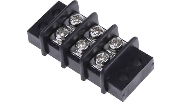
How the screw clamp works
Tightening the screw drives a clamping yoke (or lifting cage) downward, pressing the conductor firmly against the brass current bar. The joint is held by the clamping force of the screw, not by the wire touching metal casually. When torqued to the datasheet value, a screw clamp produces a gas-tight, low-resistance contact capable of carrying the block's full rated current.
Where screw blocks are used
Power distribution, motor control cabinets, building wiring, lighting, appliances, and general industrial control — anywhere installers already carry a standard screwdriver and expect to terminate solid, stranded, or flexible wires interchangeably.
Strengths
High, well-understood clamping force across a wide wire range.
Accepts every conductor type — solid, stranded, and flexible, with or without ferrules.
Familiarity — every electrician knows how to terminate one; minimal training.
Cost-effective and available in an enormous range of pitches and pole counts.
Watch-outs
They can loosen under sustained vibration or repeated thermal cycling if not torqued correctly (which is why spring technology exists).
Termination is slower than push-in, and over-tightening can damage fine-stranded wire.
Antong examples: Our feed-through terminal blocks family includes U-type, V-type and H-type 12-way screw blocks in PA66, PP, PE, PVC and bakelite housings — including VDE-certified (German/European) and NF-certified (French) variants for regulated markets.
Spring-Cage Terminal Blocks
A spring-cage terminal block (also called a tension-clamp or spring-clamp block) replaces the screw with a preloaded stainless-steel spring cage.
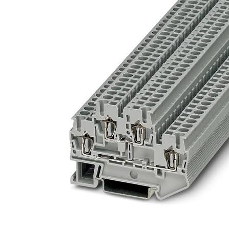
How it works
You insert a screwdriver or operating tool to lever the spring open, feed the wire into the cage, and withdraw the tool. The spring closes automatically and keeps a near-constant contact force on the conductor for the life of the connection — there is no torque value to set and, in normal service, no re-tightening schedule.
Where they win
High-vibration equipment: machine tools, trains, wind turbines, mobile machinery, ships. The spring self-compensates for thermal expansion, contraction, and conductor creep.
High-volume panel shops that want consistent terminations independent of operator strength.
Maintenance-free installations where re-opening panels is expensive.
Trade-offs
Ferrules are strongly recommended for fine flexible wire to keep strands from splaying.
Slightly higher piece price than an equivalent screw block.
A small operating tool is required.
Rule of thumb: if a screw block on the same machine has ever been found loose during inspection, that circuit is a candidate for spring-cage technology.
Push-In Terminal Blocks
Push-in (push-button) terminal blocks are the fastest manual connection technology available today.
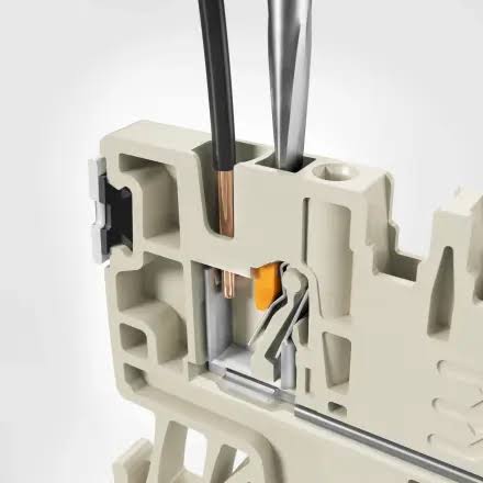
How it works
The internal spring is held open by the geometry of the entry channel. A solid conductor, or a flexible conductor fitted with a ferrule, is simply pushed in by hand — no tool — and the spring locks onto it. To release it (or to insert unferruled flexible wire), you press the integrated operating button with a screwdriver to open the spring.
Where they win
Series and high-volume panel building, where shaving seconds off every termination compounds across thousands of points.
Clean, repeatable, low-skill-dependent wiring with an audible/tactile "seated" confirmation.
Limits to design around
Unferruled flexible wire generally cannot be pushed in directly — the button/tool is needed, erasing some of the speed advantage.
Higher piece cost than screw or standard spring blocks.
The wire and ferrule must be correctly sized; a badly crimped ferrule defeats the benefit.
Push-in is a refinement of spring technology rather than a different physics: both maintain contact with a stainless spring, but push-in removes the operating step for prepared conductors.
Bolt-Type (Stud) Terminal Blocks for High Current
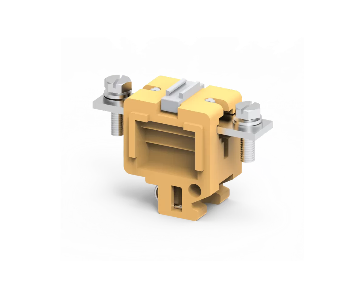
Once conductors exceed roughly 35–50 mm², screw and spring cages become impractical. Bolt-type or stud terminal blocks take over for the high-current range.
How they work
The wire is terminated with a cable lug (ring or fork terminal) and bolted directly onto a heavy copper busbar with a nut, washer, and specified torque. The large metal mass and bolted clamp deliver:
Very high current capacity — commonly up to 185 mm² and beyond (the IEC standard range runs to 300 mm²).
Exceptional short-time withstand current: IEC 60947-7-1 requires a block to withstand 120 A/mm² of rated cross-section for 1 second, a demand bolted connections meet comfortably.
A connection that can be torqued, locked, and visually verified for transformer, busbar, and main-feeder duty.
Typical applications
Main power distribution, transformers, battery banks, large drives, generator connections, and any feeder where a pulled-out wire would be a serious event. A calibrated torque wrench and the correct lug are mandatory — this is not a "firm hand-tight" connection.
For single-pole high-current distribution, Antong's junction connector line includes PA66 single-pole blocks (e.g., the LT-35 for 35 mm² conductors) and a DIN-rail 160 A terminal distribution box with multiple outgoing ways.
Barrier Terminal Blocks
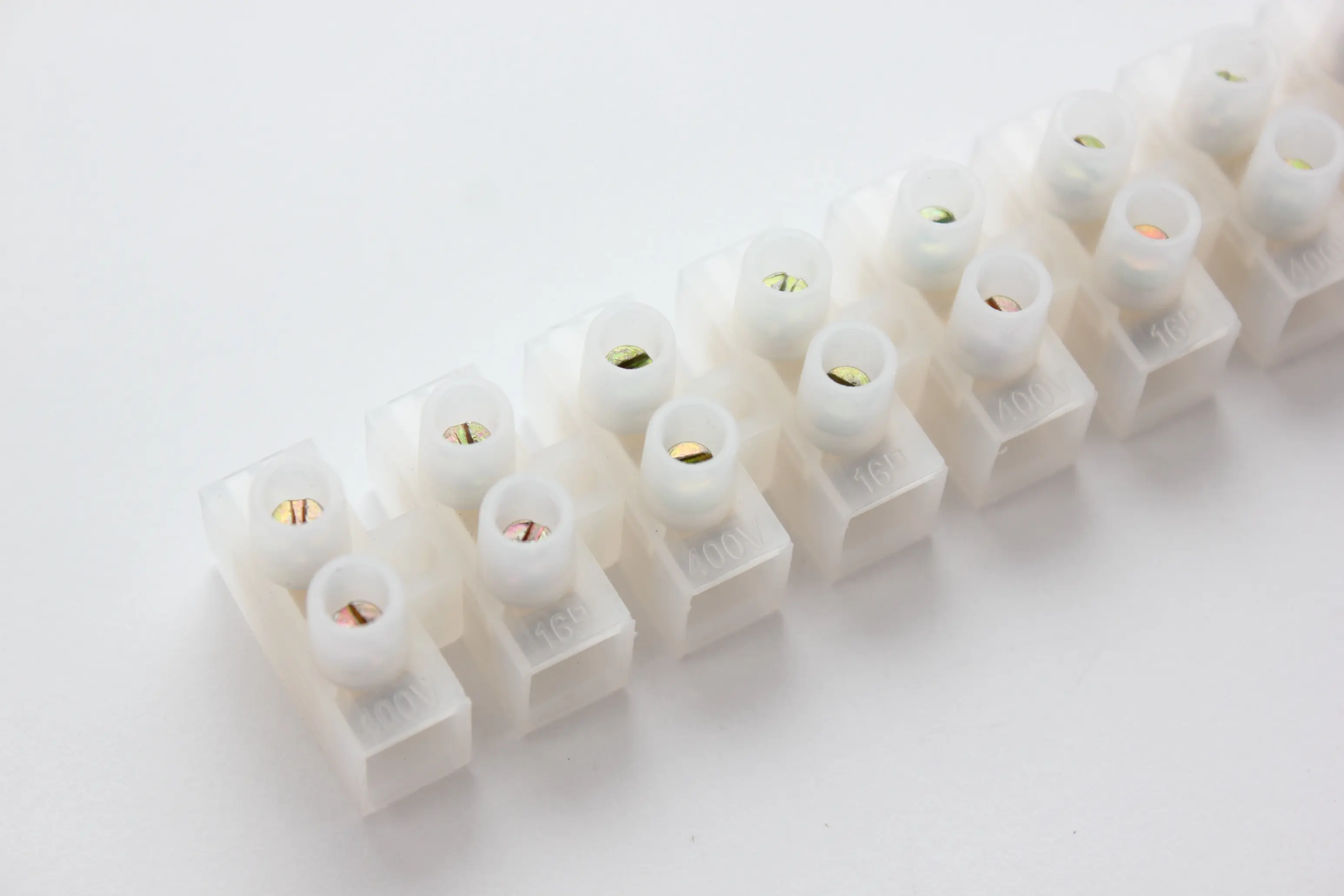
Barrier terminal blocks (barrier strips) are the dominant North American field-wiring style and are also common in power supplies and motor controls worldwide.
Design
Each pole sits in its own walled "cell" separated by raised barriers that prevent flashover and stop a stray strand from bridging adjacent circuits. Wires terminate under a screw with a washer (or under a captive clamping plate); many versions ship with a protective lid/cover. They are panel- or chassis-mounted by flanges rather than clipped to DIN rail.
Where they are used
High-current field wiring where robust, lidded, touch-safe terminations are required.
North American control panels built to UL 508A, HVAC equipment, power supplies, and older machinery.
Circuits where different voltages sit side by side and extra creepage/barrier protection is wanted.
Strengths and limits
Barrier blocks tolerate large wire, repeated field re-termination, and abuse better than most; they are, however, wider per pole than DIN rail blocks and slower to wire densely. If your panel is metric and rail-based, a DIN feed-through block is usually the better mechanical fit.
DIN Rail Terminal Blocks
Strictly, "DIN rail" describes a mounting method, not a clamping technology — but in practice it is one of the categories buyers shop, so it deserves its own treatment.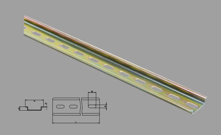
The rail standard
Most modular terminal blocks clip onto a 35 mm top-hat rail (TS35) standardized under IEC 60715 / EN 60715 (profile TH 35-7.5). Narrower 15 mm rails and older 32 mm (G32) profiles exist for specific equipment. Blocks snap onto the rail with a spring-loaded foot and lock together side by side; end brackets anchor the stack and jumpers/commoning links bridge adjacent poles.
The families that live on the rail
Feed-through blocks — a straight in-and-out connection, the workhorse of every cabinet.
Multi-level (double-/triple-deck) blocks — stack two or three circuits vertically to save rail length.
Function terminals — fused, disconnect/test, diode, and sensor/actuator blocks in the same footprint.
Protective-earth (PE) blocks — green-yellow blocks that make a defined metal-to-rail earth contact.
DIN rail mounting gives you a uniform footprint, tool-free reconfiguration, and dense, orderly panels — which is why it is the default in modern industrial control worldwide.
PCB Terminal Blocks
PCB-mount terminal blocks bring field wiring onto a printed circuit board. Instead of a rail foot, they have solder pins or tails inserted and wave-/reflow-soldered into board holes (or SMD variants for surface mount).
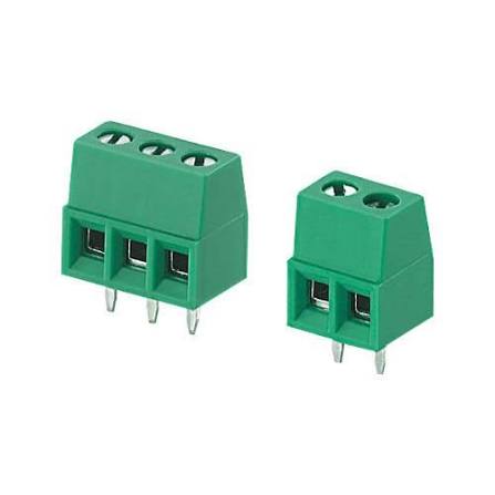
They are specified by pitch — the center-to-center distance between poles. Common pitches include 3.5 mm, 3.81 mm, 5.0 mm, 5.08 mm, 7.5 mm/7.62 mm, and 10 mm; tighter pitches suit low-level signals, while 7.5–10 mm pitches carry board-level power. They come in screw, spring, and push-in clamp styles and in horizontal (180°), vertical (90°), or angled wire-entry orientations.
Choose them when the end product is a board-level device — a controller, driver, power supply, or appliance PCB — and the connection must survive field installation and service. Key checks are pin layout against your PCB footprint, rated current for the pin cross-section, and whether the board-side solder joint can survive the wire's pull.
Pluggable Terminal Blocks
A pluggable terminal block splits into two halves: a header soldered to the PCB (or panel) and a mating plug that carries the screw/spring/push-in wire clamps. The plug mates and un-mates like a connector.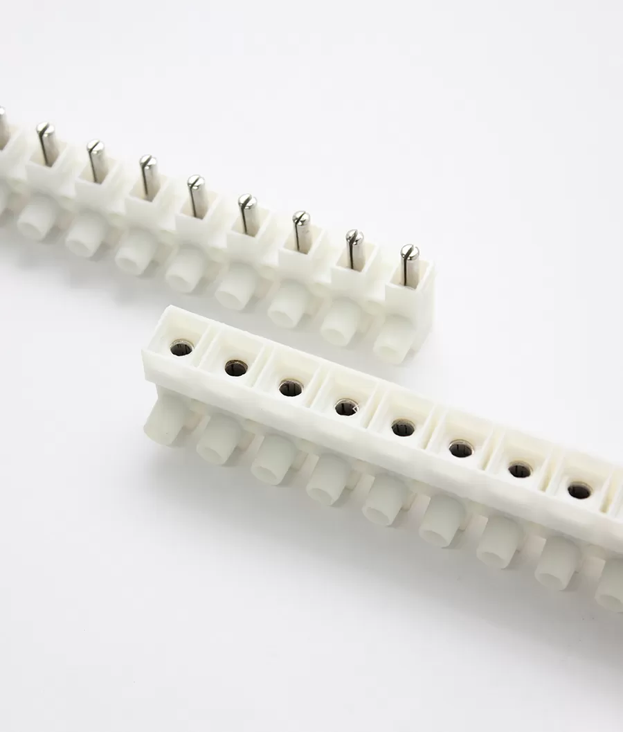
Why they are used
Modular wiring and fast servicing: a whole harness disconnects in one motion instead of unwiring every pole.
Error-free reassembly: keyed and coded options prevent a plug going onto the wrong header.
Factory pre-assembly: harnesses can be built and tested off the machine, then plugged in at final assembly.
They are the natural choice for modular machines, removable sub-assemblies, and any device that ships in sections or needs frequent field swap-out. Specify mating pairs together (header + plug, same pitch and pole count) and confirm locking/flange style.
Specialty Terminal Blocks
Beyond basic through-connection, a mature product range adds function inside the same modular footprint:
Fused terminal blocks — integrate a fuse holder so overcurrent protection sits at the point of connection, with blown-fuse indication options.
Disconnect / knife-disconnect and test blocks — an openable link isolates a circuit for measurement or maintenance without removing wires; test blocks let meters plug into current-transformer circuits safely.
Sensor/actuator (3-wire) blocks — dedicated layouts for the signal/+24 V/0 V trio of proximity sensors and valves.
Multi-level blocks — double or triple decks compress wiring density.
Protective-earth (PE) blocks — defined, low-impedance connection to the DIN rail.
Diode and component terminals — integrate a diode, resistor, or LED indicator.
Distribution blocks and busbar terminals — one input fanned to several outputs (see the 160 A rail distribution box noted earlier).
For fixed multi-pole groups, Antong also makes panel-mount unipolar terminal blocks in 8-pole and 10-pole formats, where each pole is an independent isolated connection with its own mounting flange.
Terminal Block Comparison Table
This original table summarizes how the connection technologies and mounting families compare. Treat current figures as ranges to orient you — the binding values are always on the manufacturer's datasheet.
| Type | Connection method | Tool to wire | Typical wire range | Vibration resistance | Wiring speed | Relative cost | Best application |
|---|---|---|---|---|---|---|---|
| Screw-type | Screw-driven yoke clamps wire to current bar | Screwdriver | 0.2–120 mm² (AWG 24–4/0) | Moderate; check torque after vibration | Medium | Low–Medium | General industry, power distribution, building wiring (universal default) |
| Spring-cage | Preloaded stainless spring cage | Small lever tool | 0.2–35 mm² | High; self-compensating, maintenance-free | Fast | Medium | Vibration, machines, transport, maintenance-free installs |
| Push-in | Hand insertion for solid/ferruled wire | None (tool for unferruled flex) | 0.2–35 mm² | High | Fastest | Medium–High | High-volume panel building, series production |
| Bolt/stud | Cable lug bolted to copper busbar | Torque wrench | 35–300 mm² (to 600 kcmil) | Very high | Slow | High | Main feeders, transformers, high-current distribution |
| Barrier | Screw + washer in walled cells, often lidded | Screwdriver | Up to high current | High | Slow–Medium | Medium | North American field wiring, UL 508A panels, mixed voltages |
| DIN rail (mounting) | Hosts screw/spring/push-in/function blocks on TS35 rail | Per clamp type | Full range | Per clamp type | Fast to assemble | Low–Medium | Modern control cabinets, modular, dense wiring |
| PCB-mount | Solder pins to board; screw/spring/push-in field side | Per clamp type | Board-level, ~0.2–16 mm² | Per clamp type | Medium | Low | Controllers, power supplies, board-level devices |
| Pluggable | Wire-side plug mates board-side header | Per clamp type | Board-to-medium | Per clamp type | Fastest service/replacement | Medium | Modular machines, quick-disconnect harnesses |
| Specialty | Fused/disconnect/multi-level/PE/distribution | Per base type | Varies by function | Per base type | — | Medium | Added function at the connection point |
How to Choose the Right Terminal Block: A 6-Step Framework
Selection is a narrowing process. Work through it in this order and the type almost picks itself.
Step 1 — Start with current and conductor cross-section. Find your load current and the wire size it requires. The block's rated cross-section must cover that wire, and its rated current (proven by temperature-rise test) must exceed the load with margin. This single step already rules types in or out: below ~35 mm² everything is possible; above ~50 mm² you are in bolt/stud territory. See Terminal Block Current Rating: A Complete Guide.
Step 2 — Set the voltage and isolation requirements. Match the rated insulation voltage (Ui) and impulse withstand voltage (Uimp) to your system, and check creepage/clearance for pollution degree and overvoltage category. Mixed-voltage circuits may need barriers or multi-level separation.
Step 3 — Define the environment.
Vibration / shock / thermal cycling → spring-cage or push-in over screw.
Ambient temperature and heat → check derating and housing material (PA66 is the workhorse; PBT/PC for specific thermal or mechanical needs).
Flammability → UL 94 V-0 housing and an appropriate glow-wire rating.
Dust/moisture/chemicals → required IP degree and material resistance.
Step 4 — Choose the mounting style. DIN rail (TS35) for modular cabinets; panel/flange mount (including barrier and unipolar strips) for fixed field wiring; PCB pins for board-level devices; pluggable pairs for modular disconnect.
Step 5 — Choose the connection technology. Screw for maximum flexibility and lowest cost; spring for vibration and freedom from re-torquing; push-in for wiring speed with ferruled/solid conductors in volume. Be honest about whether your production uses ferrules — it decides whether push-in delivers its speed.
Step 6 — Confirm certifications and total cost. Match approvals to the destination market: IEC/CE for most of the world, UL for North America, plus specific marks such as VDE (Germany) and NF (France) where specified. Then count total cost — piece price plus wiring labor plus lifetime maintenance — not just the unit cost.
Selection checklist: current ✓ · wire size ✓ · voltage ✓ · environment ✓ · mounting ✓ · clamp technology ✓ · certifications ✓ · total installed cost ✓.
Frequently Asked Questions
What is the most common terminal block type?
The screw-type DIN rail terminal block is the most common worldwide because it accepts all conductor types, covers the broadest current range, is inexpensive, and every electrician already knows how to terminate it. In North American field wiring, barrier strips are especially common; in high-volume modern panel shops, push-in is the fastest-growing type because of its wiring speed.
Can you mix terminal block types on the same DIN rail?
Yes. Different screw, spring, push-in, PE, and function blocks from a consistent modular series can sit side by side on the same TS35 rail, since they share the same rail profile and footprint geometry. Just anchor the stack with end brackets, confirm adjacent blocks are rated for their own circuits, and take care when commoning with jumpers — jumpers are matched to a specific series and pitch.
Which terminal block is best for high vibration?
Spring-cage or push-in types. Their stainless springs maintain near-constant contact force and self-compensate for vibration, thermal cycling, and conductor settlement, so they do not rely on a torque value that can relax. Bolt/stud connections with correctly torqued, locked hardware also suit high-current, high-vibration feeders. Plain screw blocks are the least preferred in sustained vibration unless re-torquing is scheduled.
What is the difference between a terminal block and a connector?
A terminal block is typically a fixed, reusable, inspectable junction mounted to a rail, panel, or board, terminated with a tool or by hand. A connector is usually designed to be mated and un-mated repeatedly (like the plug/header pair in pluggable terminal blocks). Pluggable terminal blocks deliberately combine both ideas.
Can I connect aluminum conductors?
Most terminal blocks certified to IEC 60947-7-1 are designed for copper conductors (the standard's title says so explicitly). Aluminum has different creep and oxidation behavior and requires blocks specifically approved and marked for it. Never assume a copper-rated block accepts aluminum — check the datasheet.
Why do IEC and UL ratings differ for the same part?
IEC and UL use different test methods, conductor references (mm² vs AWG), and temperature-rise rules, so the same physical terminal block can carry a different stated current and voltage under each regime. Both are valid within their own market; specify the rating that matches where the equipment will be certified and sold.
Next Steps: Choosing the Right Terminal Block
Picking the type is the first decision; matching an exact series, pitch, current rating, and certification to your bill of materials is the second. Here is how Antong can help:
Browse the range — explore the complete terminal blocks and connectors catalog, including feed-through blocks, unipolar blocks, and high-current junction connectors.
Request the full catalog — get dimensional drawings, rated currents, material data, and certification details for every series.
Order samples — validate fit, wire entry, and torque on your actual panel before committing to volume.
Talk to engineering — send your current, wire size, rail space, environment, and target-market certifications, and our engineers will recommend a specific series.
Antong has manufactured terminal blocks since 1989, operating a 55,000 m² facility with ISO 9001 quality management and shipping to 70+ countries. We support OEM/ODM branding, custom pole counts, and material options (PA66/PP/PE/PVC/bakelite) — and you can also reach us through our official Alibaba store for sample orders.
References & standards
IEC 60947-7-1:2009 (Edition 3), Low-voltage switchgear and controlgear — Part 7-1: Ancillary equipment — Terminal blocks for copper conductors — IEC Webstore
IEC 60947-7-1:2025 (Edition 4, current) — same title; extends the conductor range down to 0.05 mm²/30 AWG and supersedes the 2009 edition — IEC Webstore
IEC 60715 / EN 60715, Dimensions of low-voltage switchgear and controlgear — Standardized mounting on rails (TS35 top-hat rail)
UL 1059, Standard for Terminal Blocks — UL Solutions
UL 508A, Standard for Industrial Control Panels
WAGO, Material Specifications (PA66/PBT/PC, CTI, RTI, UL 94) — wago.com
Phoenix Contact, Terminal Block Material Tests (glow-wire, ball-pressure, flammability) — phoenixcontact.com
Antong product documentation — safetypass.com
Technical content prepared by the Antong Engineering Team from 35+ years of terminal block manufacturing experience. Rated values must always be confirmed against the specific product datasheet before design release.