
How to Choose Terminal Blocks: Current, Wire Size & Pitch | SafetyPass
How to Choose Terminal Blocks: Current Rating, Wire Size & Pitch
By the Antong Engineering Team · Reviewed August 2026 · 13 min read
Terminal block selection looks easy until you are staring at a datasheet and realize none of the example wires match the one on your bill of materials, the "pitch" column reads like a foreign language, and the current number you trusted turns out to be for a 40 °C cabinet you do not have.
After 35+ years of manufacturing terminal blocks and shipping them to 70+ countries, we see the same handful of selection mistakes repeat across industries — a block sized to the motor's nameplate current but not its inrush, a 2.5 mm² wire forced into a 4 mm² minimum terminal, a 5.0 mm pitch chosen for a 10 mm² feeder that then overheats the row. The fix is a method, not a bigger catalog.
This guide walks through a five-step method for choosing a terminal block: current rating → wire cross-section → pitch → voltage and isolation → environment and mounting. It ends with a printable selection checklist and the mistakes to avoid. Work through the steps in order and the correct part number almost picks itself.
Quick answer: Choosing a terminal block comes down to three numbers first. Current rating — the block's rated current (proven by temperature-rise testing to IEC 60947-7-1) must exceed your load after derating for ambient temperature and adjacent loaded blocks. Wire cross-section — your conductor must fall inside the block's minimum-to-maximum wire range (mm² or AWG), including any ferrule. Pitch — the center-to-center pole spacing must give you enough current capacity, creepage distance, and panel space. Then confirm voltage (rated insulation and impulse voltage, creepage/clearance) and the environment and mounting style. The full method is below.
In this guide
Step 1: Determine the Required Current Rating
The first number to nail down is not the wire — it is the current the block must carry continuously, plus margin for starting surges, harmonics, and future expansion.
How rated current is actually defined
Under IEC 60947-7-1, the international product standard for terminal blocks, a terminal block's rated current is not read off a wire-gauge table. The manufacturer declares a rated cross-section (from the standard's preferred sizes, 0.2 mm² to 300 mm² in the 2009 edition; the 2025 edition extends down to 0.05 mm²) and then proves a corresponding rated current by temperature-rise testing — the block is loaded and the temperature rise of its current bar and insulation must stay within limits defined by the standard.
Two practical consequences follow:
Two blocks with the same wire range can carry different rated current, because their brass cross-section, contact design, and heat dissipation differ. Design from the datasheet, not from intuition.
IEC and UL ratings can differ for the same physical part, because the test regimes differ (mm² vs AWG references, different temperature-rise rules). In North America terminal blocks are evaluated to UL 1059; specify the rating that matches where the equipment will be certified.
Browse the full all products range to see how Antong states rated current and cross-section together on every series.
Derate for ambient temperature
A block's continuous current is fundamentally a thermal limit: contact resistance converts load current into heat (I²R), and too much heat degrades the insulation and relaxes the contact over time. When the cabinet runs hotter than the reference ambient (commonly 40 °C in IEC ratings), the safe current falls.
As a planning rule, treat roughly 0.5–0.8% less continuous current per °C above the reference ambient — so a block rated at 40 °C loses on the order of 5–8% of its rating at 50 °C. The exact curve depends on the insulation material (PA66 vs PBT vs ceramic) and the block's own heat sinking, so always confirm with the manufacturer's derating data.
Derate for adjacent loaded blocks
Densely packed DIN rail blocks heat each other. When a row of blocks all carry full load, mutual heating reduces the safe current — apply the manufacturer's grouping factor (commonly in the 0.7–0.8 range for tightly packed, fully loaded rows). This is the single most overlooked derating step in panel design.
Why oversizing matters
Specifying a block comfortably above the load is cheap insurance: it lowers contact temperature, extends insulation life, tolerates inrush and load growth, and gives you margin if the ambient turns out hotter than planned. Under-sizing, by contrast, fails slowly — as heat and oxidation, not as a sudden trip.
Step 2: Match Wire Cross-Section (AWG/mm²)
Once you know the current, find the conductor cross-section that carries it, then pick a block whose wire range covers that conductor.
mm² and AWG
Metric systems specify wire in mm²; North American systems use AWG. The same block lists both. The table below is an orientation reference linking cross-section, approximate AWG, and typical IEC continuous current for the feed-through class — the binding value is always the specific product datasheet.
| Conductor cross-section | Approx. AWG | Typical continuous current (IEC, 40 °C ambient) |
|---|---|---|
| 0.5 mm² | 20 | ~6 A |
| 0.75 mm² | 18 | ~12 A |
| 1.0 mm² | 17 | ~13.5 A |
| 1.5 mm² | 16 | ~17.5 A |
| 2.5 mm² | 14 | ~24 A |
| 4 mm² | 12 | ~32 A |
| 6 mm² | 10 | ~41 A |
| 10 mm² | 8 | ~57 A |
| 16 mm² | 6 | ~76 A |
| 25 mm² | 4 | ~101 A |
| 35 mm² | 2 | ~125 A |
| 50 mm² and above | 1/0 and larger | Bolt/stud territory |
Solid vs stranded vs flexible
Solid wire seats cleanly and holds well in screw, spring, and push-in terminals.
Stranded wire is flexible and common in panel building; it should be twisted clean and, where the block or standard calls for it, terminated with a ferrule.
Flexible (fine-stranded) wire must be protected from splaying — a ferrule is strongly recommended for screw clamps and mandatory for tool-free push-in insertion.
Minimum and maximum wire range
Every terminal block has a wire range — for example "0.5–6 mm²" — and both ends matter. A wire below the minimum makes a poor, loose contact; a wire above the maximum will not enter the entry or seat fully against the current bar. Check the range on both the wire side and, for multi-conductor blocks, every pole.
Using ferrules
A correctly sized ferrule binds fine strands into a uniform, solid-like cross-section that protects the wire and improves contact area. But a ferrule changes the effective diameter, so a ferrule that is the wrong size for the terminal defeats the benefit. Match ferrule to wire, then confirm the ferrule + wire assembly still fits the block's wire range — and note that ferrules are effectively mandatory for push-in blocks with flexible wire.
Step 3: Select the Correct Pitch
Pitch is the center-to-center distance between adjacent poles of a terminal block. It is the dimension that ties current, isolation, and panel space together.
What pitch does
A wider pitch buys you three things at once: more room for a heavier current bar (higher current), more creepage distance between poles (higher voltage withstand), and easier wiring with larger conductors. The price is panel space — wider pitch means fewer connections per rail length or board width.
Common pitches and where they land
| Pitch (mm) | Metric/imperial note | Typical use |
|---|---|---|
| 3.5 / 3.81 | — | Low-level signals, compact PCB I/O |
| 5.0 / 5.08 | 5.08 = 0.2 in | PCB control and signal power |
| 7.5 / 7.62 | 7.62 = 0.3 in | Board-level power, motor and driver wiring |
| 10 / 10.16 | 10.16 = 0.4 in | Higher board-level power, larger conductors |
| 13.0 | — | Heavy power terminals, large cross-sections |
The 5.08 / 7.62 / 10.16 mm "imperial" pitches are simply the 0.2 / 0.3 / 0.4 inch grid translated to millimetres — you will see both spellings on the same product line.
Pitch vs current density and panel space
Because pitch governs the current-bar cross-section that fits between poles, it also sets a practical ceiling on current. Tight 3.5–5.0 mm pitches are fine for signal and control wiring; 7.5–10 mm pitches carry board-level power; heavy feed-through and bolt-type blocks use wider spacing (or single-pole formats) to fit 25 mm² and larger conductors. On a DIN rail, the equivalent lever is the block width per pole — narrower blocks pack more poles per metre but dissipate less heat.
A practical test: if you find yourself trying to squeeze a conductor into a block whose pitch feels too tight, you have likely skipped from Step 2 back to Step 3 — the pitch and the wire size are a matched pair, not independent choices.
Step 4: Consider Voltage Rating and Creepage/Clearance
Current is about heat; voltage is about isolation — keeping potential differences from arcing or tracking across the block.
The three numbers to check
Rated insulation voltage (Ui) — the continuous working voltage the insulation is designed for.
Rated impulse withstand voltage (Uimp) — the block's ability to survive transient overvoltages (lightning, switching surges), tied to the system's overvoltage category. Both Ui and Uimp are defined in IEC 60947-1, the general rules for low-voltage switchgear.
Creepage and clearance — clearance is the shortest distance through air between live parts; creepage is the shortest distance along the surface of the insulation. Creepage is usually the limiting one for tracking, so it scales with the insulation's material group.
Pollution degree and material group (CTI)
The required creepage distance depends on the pollution degree of the installation (IEC 60947-1 defines degrees 1–4, from clean/dry to conductive dust/condensation) and on the comparative tracking index (CTI) of the insulation material, measured to IEC 60112. Materials are grouped by CTI:
Group I — CTI ≥ 600 (high resistance to tracking)
Group II — 400 ≤ CTI < 600
Group IIIa — 175 ≤ CTI < 400
Group IIIb — 100 ≤ CTI < 175
A higher material group permits a smaller creepage distance for the same voltage — one reason a PA66 block and a cheaper, lower-CTI plastic can look identical yet carry different voltage ratings. When you mix voltages side by side, choose a barrier-style or higher-group block to maintain safe separation.
Step 5: Environment and Mounting
The last step is where the block physically lives and how it attaches.
Environment
Temperature range — confirm the housing material's continuous-use temperature and re-check derating from Step 1.
Vibration and shock — for sustained vibration choose spring-cage or push-in over screw (see our screw vs spring vs push-in comparison).
Ingress protection (IP rating) — open terminal blocks are typically IP20 (finger-safe); sealed enclosures or junction boxes carry the higher IP rating, not the block itself.
Flammability — a UL 94 V-0 housing and an appropriate glow-wire rating for the end application.
Mounting style
DIN rail (TS35) — the default for modern control cabinets, standardized to IEC 60715 / EN 60715. Blocks clip on, lock together, and are reconfigured tool-free. See the full terminal block types guide.
Panel / flange mount — barrier strips and fixed multi-pole blocks screw to a chassis for field wiring.
PCB mount — solder pins bring field wiring onto a board; pitch becomes the critical footprint dimension.
Pluggable — a wire-side plug mates a board-side header for modular, quick-disconnect wiring.
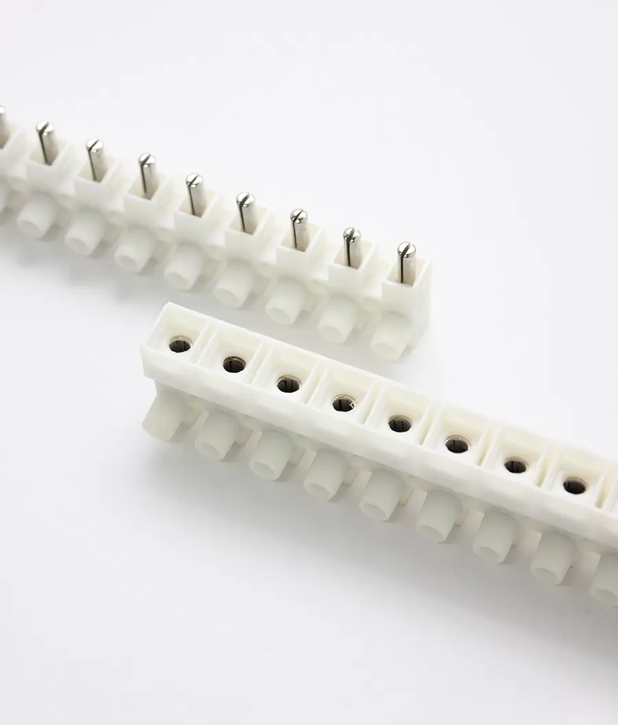
Antong's feed-through terminal blocks cover the DIN-rail and panel-mount workhorses in PA66, PP, PE, PVC and bakelite housings, while the one side entry screws connector range suits fixed, side-entry wiring and the unipolar terminal blocks provide independent 8-pole and 10-pole isolated connections.
Terminal Block Selection Checklist
Copy or print this checklist and walk it top to bottom. Every field must be filled before a part number is finalized.
| # | Parameter | Decision / value to record |
|---|---|---|
| 1 | Load current (continuous + peak/inrush) | ______ A |
| 2 | Rated current after ambient derating | ______ A |
| 3 | Rated current after grouping derating | ______ A |
| 4 | Conductor cross-section (mm² / AWG) | ______ |
| 5 | Conductor type (solid / stranded / flexible) | ______ |
| 6 | Ferrule required? (size) | ______ |
| 7 | Wire range of candidate block | ______ – ______ mm² |
| 8 | Pitch / block width | ______ mm |
| 9 | Rated insulation voltage Ui / impulse Uimp | ______ V / ______ kV |
| 10 | Pollution degree / material group (CTI) | Degree ______ / Group ______ |
| 11 | Environment (temp, vibration, IP, flammability) | ______ |
| 12 | Mounting style | DIN rail / panel / PCB / pluggable |
| 13 | Certifications (IEC/CE, UL, VDE, NF…) | ______ |
| 14 | Total installed cost (part + labor + maintenance) | ______ |
The checklist distills the five steps into a single pass. If any line is blank, the selection is not finished.
Common Selection Mistakes to Avoid
1. Undersizing for ambient temperature
Rating the block for the load but not for a hot enclosure is the most common failure we see. A cabinet that runs at 50 °C — sun-loaded outdoor gear, compact panels, ovens, drives with poor ventilation — needs a derated rating. Re-run Step 1 with the real ambient, not the room-temperature test bench.
2. Ignoring derating for adjacent terminals
A single block on the bench carries its rated current; a row of twenty blocks all loaded together does not. Apply the grouping factor to fully loaded, tightly packed rows, and add ventilation or spacing for the heaviest feeders.
3. Mismatching the wire ferrule size
A ferrule that is too small leaves strands loose inside it; too large and it will not seat in the terminal. This shows up as intermittent, overheating connections that pass a visual check. Match ferrule to wire, crimp with the correct tool, and confirm the finished assembly fits the block's wire range — especially for push-in terminals, where the ferrule is what makes tool-free insertion work at all.
FAQ: Frequently Asked Questions
What happens if I use a terminal block below its rated wire size?
Using a conductor below the block's minimum wire range makes a poor, loose contact — the clamp cannot compress the wire fully against the current bar, so contact resistance rises, the joint heats under load, and the connection degrades over time. (A wire above the maximum simply will not fit or seat correctly.) Always keep the conductor inside the block's stated minimum-to-maximum range, and remember a ferrule changes the effective diameter.
How much should I derate terminal blocks at 50 °C?
Most terminal blocks are rated at a 40 °C ambient reference. At 50 °C you are 10 °C above that. Using a conservative 0.5–0.8% per °C planning rule, expect to reduce continuous current by roughly 5–8%. The exact figure depends on the insulation material (PA66 vs PBT vs ceramic) and the block's heat dissipation, so confirm against the manufacturer's derating curve — and do not forget the additional grouping derating if blocks are packed in a row.
Is higher current rating always better?
No — bigger is not automatically better. A higher-rated block is physically larger: wider pitch, more panel or board space, higher unit cost, and sometimes a wire range whose minimum is above your small signal wire. The right block is the one whose rating covers your load with margin while matching your wire size, pitch, and space constraints. Overspecifying by one step is sensible; overspecifying by several steps wastes space and money without adding safety.
Next Steps: Choosing the Right Terminal Block
The five steps turn a vague requirement into a filled-in checklist; the last step is matching that checklist to an exact series, pitch, rating, and certification. Here is how Antong can help:
Browse the range — explore the complete all products catalog, including feed-through terminal blocks, one side entry screws connectors, and unipolar terminal blocks.
Request the full catalog — get dimensional drawings, rated currents, wire ranges, pitches, material data, and certification details for every series.
Order samples — validate wire fit, torque, and temperature on your actual conductors and enclosure before committing to volume.
Talk to engineering — send your load current, wire size, pitch constraint, environment, and target-market certifications, and our engineers will recommend a specific series.
Antong has manufactured terminal blocks since 1989, operating a 55,000 m² facility with ISO 9001 quality management and shipping to 70+ countries. We support OEM/ODM branding, custom pole counts, and material options — and we are happy to review your checklist line by line so the part number you order is the one your application actually needs.
Continue reading
References & standards
IEC 60947-7-1, Low-voltage switchgear and controlgear — Part 7-1: Ancillary equipment — Terminal blocks for copper conductors — IEC Webstore
IEC 60947-1, Low-voltage switchgear and controlgear — Part 1: General rules — IEC Webstore
IEC 60112, Method for the determination of the proof and the comparative tracking indices of solid insulating materials — IEC Webstore
IEC 60715 / EN 60715, Dimensions of low-voltage switchgear and controlgear — Standardized mounting on rails (TS35 top-hat rail)
UL 1059, Standard for Terminal Blocks — UL Solutions
WAGO, Material Specifications (PA66/PBT/PC; CTI, RTI, UL 94) — wago.com
Phoenix Contact, Terminal Block Material Tests (glow-wire, ball-pressure, flammability) — phoenixcontact.com
Antong product documentation — safetypass.com
Technical content prepared by the Antong Engineering Team from 35+ years of terminal block manufacturing experience. Current, cross-section, derating, and pitch figures are orientation benchmarks; rated values must always be confirmed against the specific product datasheet before design release.