
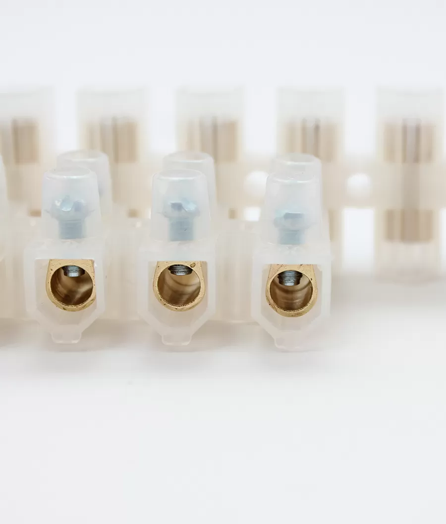
Feed-Through Terminal Blocks: A Complete Overview | SafetyPass
Feed-Through Terminal Blocks: A Complete Overview
By the Antong Engineering Team · Reviewed August 2026 · 11 min read
Selecting the right feed through terminal block requires more than matching a familiar catalog name. Products in the same category can differ in current path, conductor interface, material, dimensions, mounting and approval conditions.
For panel builders and distributors, that distinction affects initial design, purchasing, assembly and later maintenance. This guide follows the original brief from construction through ratings, applications and practical checks so the same evidence can support the RFQ, sample approval and inspection record.
From more than 35 years of manufacturing terminal blocks, the consistent lesson is that reliability comes from matching the complete application rather than one attractive number. IEC 60947-7-1 ties rated current to a declared cross-section and temperature-rise test rather than appearance alone.
Quick answer: A feed-through terminal block joins an incoming and outgoing conductor through one insulated current bar. Select it by rated current, conductor range, voltage, clamp type, housing material, mounting method and compatible accessories; never assume that two products with the same wire size have the same tested rating.
In this guide
What Is a Feed-Through Terminal Block?
A feed-through terminal block joins an incoming and outgoing conductor through one insulated current bar. A useful definition also identifies the boundary of the category, separating a Feed-Through Terminal Block from similar-looking connection or mounting systems.
Basic construction: housing, current bar, two wire entries
The datasheet or drawing should identify basic construction and state housing, current bar, two wire entries. Current-bar cross-section, clamp geometry, insulation and mounting all contribute to the finished terminal. A change to one component can alter rating, fit or service life. Do not copy the value from a neighboring series unless the manufacturer documents the same construction and approval.
How it differs from other terminal types
Compare the alternatives on the same axes: function, current path, conductor, mounting, rating, service method and approval. Judge both alternatives under the same load, conductor, mounting and service conditions. Similar appearance or one shared dimension does not establish equivalent function or approval. Keep the evidence with the drawing and sample record so purchasing cannot substitute a similar-looking part.
Construction and Materials
This section explains construction and materials and identifies the values that need to be fixed on the drawing, datasheet or RFQ. A change in one value can alter fit, rating or service access.
PA66 housing, copper alloy current bar, steel/copper clamp
Current-bar cross-section, clamp geometry, insulation and mounting all contribute to the finished terminal. A change to one component can alter rating, fit or service life. Antong catalog examples in the SPV feed-through family pair each wire range with its own 450 V or 500 V rating and 17.5 A to 76 A class values.
Surface plating: tin, zinc, nickel
The datasheet or drawing should identify surface plating and state tin, zinc, nickel. Separate the material family from the exact alloy or resin grade. Conductivity, strength, temperature, flame behavior and corrosion performance can change with grade, plating, molding and finished geometry. Record the accepted condition in the terminal schedule so installers and inspectors use the same basis.
Standard Sizes and Ratings
This section explains standard sizes and ratings and identifies the values that need to be fixed on the drawing, datasheet or RFQ. A change in one value can alter fit, rating or service access.
2.5mm², 4mm², 6mm², 10mm², 16mm², 35mm²
Treat the stated millimeter value as one nominal dimension or conductor class; verify the complete tolerance and profile drawing. These are conductor cross-section classes, not interchangeable terminal ratings. Match each size to its own wire range, current, voltage and clamp data on the exact product row. Confirm the result on a production-representative sample before releasing tooling or volume orders.
Current ratings and wire ranges table (original)
Treat the value as a tested thermal condition rather than a number inferred from body size. Keep it paired with the declared conductor, ambient, grouping and certification system, then apply required derating. IEC 60947-7-1 ties rated current to a declared cross-section and temperature-rise test rather than appearance alone.
Common Feed-Through Size Classes
| Rated cross-section | Approx. AWG | Orientation current class |
|---|---|---|
| 2.5 mm² | 14 | ~24 A |
| 4 mm² | 12 | ~32 A |
| 6 mm² | 10 | ~41 A |
| 10 mm² | 8 | ~57 A |
| 16 mm² | 6 | ~76 A |
| 35 mm² | 2 | ~125 A |
Orientation only; use the exact model's IEC/UL datasheet and derating data.
Typical Applications
Application examples help narrow the product family, but an industry name is not an electrical rating. Translate each use case into current, voltage, conductor, temperature, vibration, enclosure and service requirements.
Control panels
One application can contain both low-energy signals and high-power circuits. Divide the wiring into duty classes and select each terminal from the conditions at that connection point. Confirm the result on a production-representative sample before releasing tooling or volume orders.
Power distribution
Start with the real duty cycle and enclosure environment, then map the application to conductor, rating, mounting and maintenance requirements. The industry label alone cannot approve the part. Keep the evidence with the drawing and sample record so purchasing cannot substitute a similar-looking part.
Machine building
The application is a starting condition, not a rating. Translate it into current, voltage, temperature, vibration, enclosure, servicing and certification requirements before choosing a product family. Antong catalog examples in the SPV feed-through family pair each wire range with its own 450 V or 500 V rating and 17.5 A to 76 A class values.
Antong Feed-Through Terminal Block Range
Antong's complete terminal blocks and connectors catalog illustrate how one named family can contain several materials, sizes and approval combinations. Use the complete item number and current drawing; do not transfer one model's rating to every variant in the range.
Product highlights with photos and key specs
State the requirement in terms that engineering, purchasing and inspection can all verify. If the catalog does not provide the needed value, request a drawing or test record before approval. Keep the evidence with the drawing and sample record so purchasing cannot substitute a similar-looking part.
Available colors and marking options
Use the visual system to support the schematic, terminal schedule and maintenance record. Color or position alone is insufficient where a marker can be hidden, changed or interpreted differently. Do not copy the value from a neighboring series unless the manufacturer documents the same construction and approval.
Related guidance: Terminal Block Types: The Complete Guide with Pictures and Screw vs Spring vs Push-in Terminal Blocks: How to Choose.
Practical Specification Workflow
Start with the circuit and installation rather than a preferred part number. Record the required function, conductor construction, continuous and abnormal current, system voltage, ambient temperature, enclosure, mounting and target-market approval. Translate every catalog phrase into a value or drawing reference that purchasing and quality teams can verify.
Next, compare candidate datasheets line by line. Keep each current or voltage value paired with its conductor, test standard and environmental condition; do not combine the most favorable values from different rows or variants. IEC 60947-7-1 ties rated current to a declared cross-section and temperature-rise test rather than appearance alone.
Finally, test a production-representative sample with the actual wire, tool, accessory and mounting. Check insertion, torque or operation, pull security, spacing, labeling and service access. Photograph the approved assembly and retain the datasheet revision so later substitutions can be evaluated against the same baseline.
FAQ: Frequently Asked Questions
What does feed-through mean in terminal blocks?
Feed-through means that one conductive bar carries current or a signal from an incoming clamp to an outgoing clamp through the insulating housing. It describes the electrical path, not the mounting style or clamp technology.
How many wires can a feed-through terminal accept?
A conventional feed-through block normally provides one conductor position on each side. More than one conductor in a clamping point is permitted only when the exact model and conductor combination are approved by the manufacturer.
Are feed-through terminals double-level?
No. Feed-through describes the through connection; single-, double- and multi-level describe how many circuits are stacked vertically. A feed-through function can exist in more than one level architecture.
Next Steps: Choosing the Right Terminal Block
Turn the guide into a short specification before requesting a quotation. Record the exact function, conductor, electrical ratings, dimensions, mounting, environment, accessories and destination-market approvals, then evaluate a sample in the real assembly.
Browse relevant products — compare feed-through terminal blocks and complete terminal blocks and connectors catalog.
Request the full catalog and drawings — keep the exact item number, revision, dimensions, ratings and accessory list together.
Evaluate production-representative samples — use the actual wire, ferrule or lug, tool, mounting and enclosure conditions.
Send a complete RFQ to engineering — include current, voltage, conductor, environment, quantity, approvals and any OEM/ODM requirements.
Antong has manufactured terminal blocks since 1989, operating a 55,000 m² production facility with ISO 9001 quality management and shipping to 70+ countries. Product parameters and certifications vary by exact model; request the current datasheet and approval evidence before releasing the bill of materials.
Continue reading
References & standards
IEC 60947-7-1, Low-voltage switchgear and controlgear — Part 7-1: Ancillary equipment — Terminal blocks for copper conductors — webstore.iec.ch
Antong product documentation, Terminal blocks, brass bars, factory and quality information — www.safetypass.com
Antong Alibaba Store, Catalog and sample-order channel — safetypass.en.alibaba.com
Technical content prepared by the Antong Engineering Team from 35+ years of terminal block manufacturing experience. Values, compatibility and approvals must always be confirmed against the exact product datasheet and applicable installation standard before design release.