
Barrier Terminal Blocks Explained: Uses, Ratings & Selection | SafetyPass
Barrier Terminal Blocks Explained: Uses, Ratings & Selection
By the Antong Engineering Team · Reviewed August 2026 · 11 min read
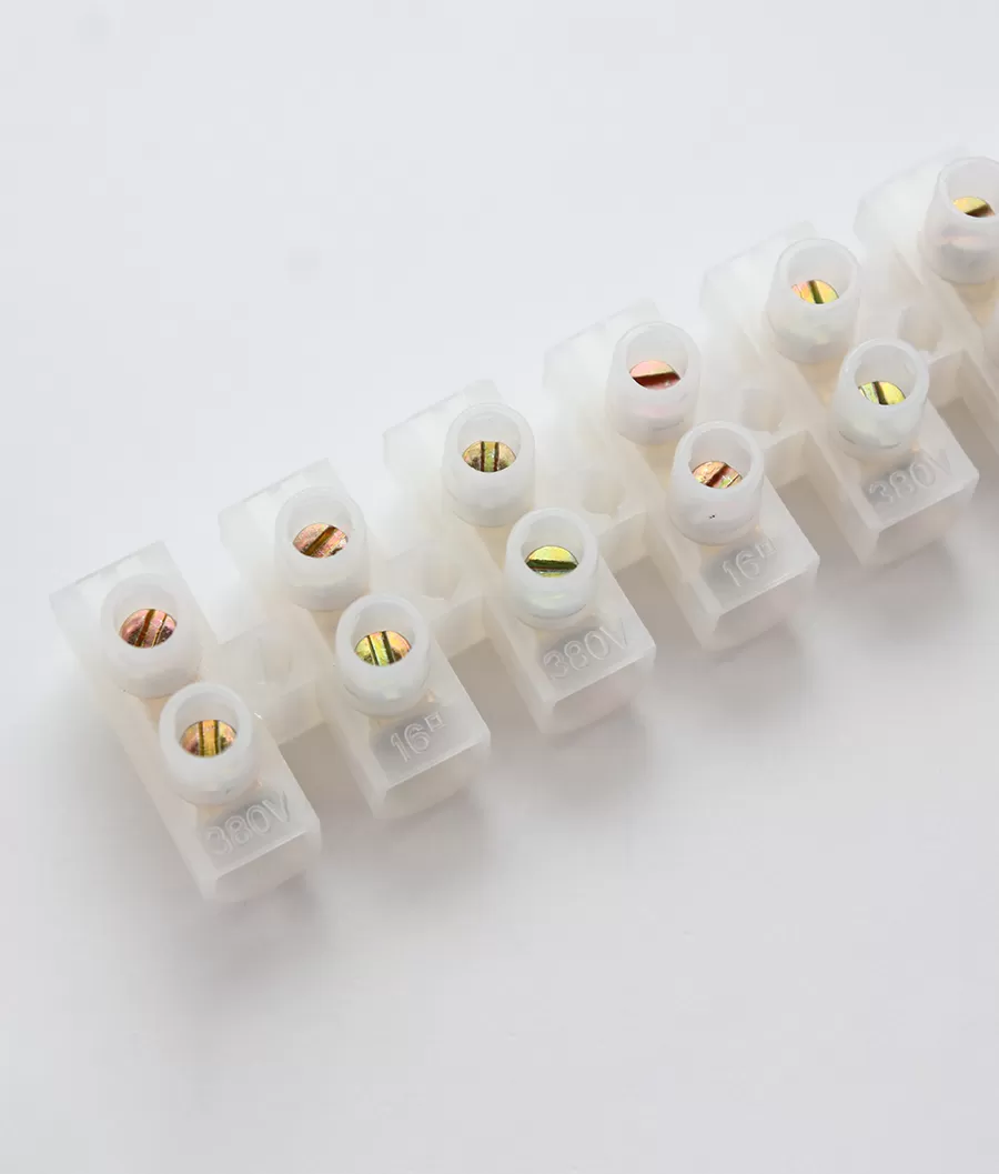
A barrier terminal block is a fixed terminal strip whose connection points are separated by raised insulating walls. Those barriers help keep tools, wire strands, and adjacent circuits apart, while screw or stud hardware creates a secure, inspectable connection. In North America, buyers commonly call the same product a barrier strip.
Barrier blocks are familiar in HVAC units, industrial controls, power supplies, motor circuits, appliances, and other equipment that brings field wiring to a chassis or printed circuit board. Their appearance is simple, but the selection is not: the same pole count can be offered at several pitches, with open or covered housings, screw or stud hardware, different conductor ranges, and different UL conditions of acceptability.
After 35+ years of terminal block manufacturing, the recurring problems we see are rarely about the number of poles. They come from treating the cover as an IP enclosure, assuming every screw accepts bare wire, or copying an IEC current value into a North American UL design. This guide explains what a barrier block is, where it belongs, and how to specify one without those mistakes.
Quick answer: Choose a barrier terminal block when you need a rugged, fixed, multi-pole termination on a panel, chassis, or PCB, especially for North American OEM equipment and field wiring. Specify the exact pole count, pitch, current and voltage ratings, conductor or lug range, screw/stud hardware, mounting pattern, housing material, cover, and certification. A lidded design improves accidental-contact and contamination protection but is not automatically sealed or IP-rated. UL recognition also applies to the exact catalog number and use conditions — not to every barrier strip that looks similar.
In this guide
What Is a Barrier Terminal Block?
A barrier terminal block is an insulating body that carries a row of electrically separate terminal assemblies. Each pole is divided from the next by a molded wall or barrier. Conductive hardware — normally a screw clamp, pressure plate, washer-and-screw assembly, or threaded stud — joins the field conductor to the internal current path or board connection.
The barriers serve three practical purposes:
Reduce accidental bridging by a screwdriver, loose wire strand, or dropped hardware.
Support creepage and clearance between adjacent poles, subject to the actual dimensions, voltage rating, pollution degree, and material properties.
Guide wiring and inspection by giving every circuit a defined position.
A taller barrier does not by itself prove a higher voltage rating. The complete product — housing geometry, material, conductive parts, mounting surface, cover, and test conditions — determines the rating.
“Barrier strip” vs “terminal block”
A terminal block is the broad category. A barrier strip is one type of terminal block, identified by its row of screw or stud terminals separated by raised insulating walls. The terms are often used interchangeably in North American catalogs, but not every terminal block is a barrier strip: DIN rail feed-through, spring-cage, push-in, pluggable, and distribution blocks use different structures.
Barrier strips are typically fixed to a panel or chassis through molded mounting holes or flanges. PCB versions replace the panel-side connection with solder pins while retaining barrier-separated field terminals. For a wider view of all connection families, see our terminal block types guide.
Key Features and Options
Two barrier blocks with the same pole count can be mechanically and electrically different. Treat the options below as part of the specification, not as cosmetic details.
| Option | What it changes | What to verify |
|---|---|---|
| Open design | Fast access for wiring, testing, and re-torquing | Required clearance, accidental-contact risk, enclosure protection |
| Lidded / covered design | Adds a removable or hinged shield over live hardware | Cover retention, tool access, flammability, and whether any IP rating is actually declared |
| Screw termination | Uses a screw, washer, pressure plate, or clamp | Bare-wire vs fork/ring-lug approval, wire range, strip length, torque |
| Stud termination | Secures ring or fork lugs with nuts and washers | Stud diameter, lug dimensions, stack order, torque, anti-rotation hardware |
| Panel / chassis mount | Fixes the strip through holes, slots, or flanges | Hole centers, fastener size, standoff height, mounting-surface strength |
| PCB mount | Uses solder pins on the board side | Pin pitch, drill pattern, solder process, board support, pull load |
Open vs lidded designs
Open barrier strips are easy to wire and probe. They work well inside a controlled enclosure where the equipment design already prevents access to live parts. Lidded versions add a physical shield against accidental tool contact, dropped metal, and light contamination.
The cover has limits. Unless the datasheet assigns an ingress-protection rating to the assembled product, a lid does not make the terminal waterproof, dust-tight, or suitable for outdoor exposure. Wire-entry openings and cover joints remain paths for contamination. The enclosure, not the terminal cover alone, normally provides environmental protection.
Screw and stud termination
Some screw terminals accept a stripped conductor under a pressure plate; others are intended for fork or ring lugs. Driving bare strands directly under a screw that was designed for a lug can cut strands, spread the conductor, or produce unstable contact pressure. Conversely, a lug can interfere with the barrier walls if its palm is too wide.
Stud versions are useful when the design calls for crimped lugs, repeated field service, or a robust high-current connection. Specify the lug hole, palm width, conductor size, washer sequence, and tightening torque together. “Fits the stud” is not enough if the lug overlaps the next barrier or cannot sit flat.
Standoffs and mounting holes
Molded feet and standoffs keep conductive parts away from the mounting surface and help establish spacing. The mounting holes control the strip's ability to withstand wire pull and installation torque. A barrier block should sit flat without twisting; a distorted body can misalign covers, terminals, and PCB pins.
Common Applications
Barrier strips are selected where installers need visible, individually separated terminations and a fixed mounting pattern.
Power distribution and power supplies
A wider-pitch barrier block can organize line, neutral, output, and control connections on a power supply or distribution assembly. Stud versions can accept crimped lugs for heavier conductors. The block must be rated for the continuous load, fault conditions, voltage, conductor type, and temperature inside the enclosure; barrier height alone is not an electrical rating.
HVAC equipment
HVAC manufacturers use barrier strips for compressors, motors, fans, heaters, thermostats, and field-control wiring. They are familiar to service technicians and can present a clear wiring schedule at the equipment boundary. A removable cover is useful where service access is frequent, provided it does not obstruct conductor bend radius or torque access.
Industrial controls and motor circuits
Barrier blocks can terminate contactors, relays, drives, sensors, and motor leads in fixed panels or machines. They are especially practical when the OEM has a repeatable drilling pattern and does not need the modularity of a DIN rail row. For high vibration, specify hardware locking, conductor preparation, torque control, and inspection intervals rather than relying on the barriers to prevent loosening.
PCB and appliance connections
PCB barrier terminals bring field wiring directly onto a board while physically separating adjacent poles. The PCB footprint, solder-pin current, copper trace width, mechanical support, and field-wire pull all need review. A terminal may be rated for more current than the board trace can safely carry.
Barrier vs DIN Rail Terminal Blocks
Barrier strips are strongly associated with North American equipment, while modular DIN rail terminals are widespread in European and international control cabinets. That is a market tendency, not a technical rule: both formats are used worldwide, and one assembly can use both.
| Consideration | Barrier terminal block | DIN rail terminal block |
|---|---|---|
| Mounting | Fixed holes or flanges on panel/chassis; some PCB versions | Clips onto an approved rail profile, commonly TS35/TH35 |
| Modularity | Pole count and spacing usually fixed in one strip | Individual blocks can be added, removed, or rearranged |
| Field familiarity | Common in North American HVAC, power supplies, and OEM equipment | Common in industrial cabinets, PLC/I/O, and modular automation |
| Connection options | Screw, pressure plate, or stud; often suited to fork/ring lugs | Screw, spring-cage, push-in, bolt, PE, fused, disconnect, and other functions |
| Current / wire range | Can favor wider pitches and lug-based power wiring | Covers signal through high-current classes, depending on series |
| Accessories | Covers, jumpers, marking strips, mounting hardware | End stops, end covers, partitions, jumpers, markers, test accessories |
| Expansion | Usually requires another strip or a changed mounting pattern | Easier within available rail length and the same modular family |
Neither format is inherently “higher current.” A wide, stud-type barrier block may outperform a compact DIN rail block, while a purpose-designed high-current rail terminal may outperform a small barrier strip. Compare the tested rating, conductor range, temperature-rise conditions, and mounting arrangement — not the product category name.
Choose a barrier strip when the chassis layout is fixed, lug wiring is preferred, or regional service practice expects screw-down field terminals. Choose DIN rail when the panel needs modular reconfiguration, dense labeling, mixed terminal functions, or future expansion. Our DIN rail terminal block guide explains the rail-based alternative, while Antong's feed-through terminal blocks provide another way to compare fixed and through-connection requirements.
Selection Criteria
Use the checklist below before approving a barrier terminal block for a bill of materials.
| Parameter | Decision to record | Common mistake |
|---|---|---|
| Pole count | Number of independent circuits plus any spare positions | Counting wires instead of electrical poles |
| Pitch | Center-to-center spacing that fits the conductor/lug and voltage requirement | Assuming all strips with the same pole count share dimensions |
| Current and voltage | Continuous current, peak/fault conditions, working and applicable UL/IEC ratings | Mixing ratings from different certification systems |
| Wire or lug range | Conductor size/type, ferrule or lug dimensions, number of conductors per terminal | Using bare wire where only lugs are approved |
| Termination hardware | Screw or stud size, washer/plate arrangement, specified torque | Tightening by feel or substituting hardware |
| Mounting | Hole centers, fastener size, standoff, PCB footprint, available height | Discovering the mounting pattern after tooling is released |
| Housing / cover | Thermoplastic or phenolic, temperature, flammability, cover access | Treating a lid as a sealed enclosure |
| Approvals | Exact model certification and conditions of acceptability | Assuming a family logo covers every pole count and variant |
Current, wire range, and pitch
Start with the continuous load and conductor size, then verify both against the same datasheet. Apply ambient-temperature and grouping derating where required. Wider pitch can provide room for larger lugs and greater spacing, but pitch is not a substitute for a tested current or voltage rating. Our terminal block current, wire-size, and pitch selection guide provides the full sequence.
For UL projects, verify the exact catalog number under UL 1059, Standard for Terminal Blocks, including field- or factory-wiring conditions, conductor range, torque, and required accessories. UL 508A applies to industrial control panels and affects how components are selected and used in the completed panel. A statement such as “designed to UL 1059” is not the same as a current UL certification for the exact model.
Phenolic vs thermoplastic housings
Phenolic (thermoset) bodies are associated with traditional barrier strips and offer dimensional stability and heat resistance, but they are generally less impact-tolerant and cannot be remelted after curing. Thermoplastic housings — such as PA/PA66, PBT, or PC depending on the design — support detailed molded barriers, covers, and color options and can offer good impact performance.
Do not select by resin name alone. Compare the declared operating temperature, flammability rating, comparative tracking performance, mechanical strength, and applicable product certification. A generic “nylon” or “bakelite” description does not establish the completed terminal block's electrical rating.
Sample evaluation before volume production
Before releasing a bulk order, test the sample with the actual wire, ferrule or lug, torque tool, panel thickness, cover, and adjacent components. Check that the conductor seats flat, the lug does not bridge a barrier, the cover closes without pressing on the wires, and the mounting body does not twist at the specified torque. Antong's complete product catalog can be used to compare terminal families before requesting drawings and samples.
FAQ: Frequently Asked Questions
What is the difference between a barrier strip and a terminal block?
A terminal block is the broad category of insulated components used to join conductors. A barrier strip is a terminal-block subtype with a row of screw or stud terminals separated by raised insulating barriers. Barrier strips are commonly panel-, chassis-, or PCB-mounted; DIN rail, spring-cage, push-in, and pluggable blocks are other terminal-block types.
Are barrier terminal blocks UL Recognized?
Some are, but not automatically. UL certification applies to the exact catalog number, construction, ratings, conductor range, torque, accessories, and conditions of acceptability. A barrier block may be UL Recognized, UL Listed for a particular use, or uncertified. Verify the product marking and current UL record against UL 1059 rather than relying on appearance or a supplier's family-level claim.
When should I use a lidded barrier block?
Use a lidded design when the application benefits from a shield against accidental tool contact, dropped hardware, or light contamination, while still requiring removable service access. Do not assume the lid makes the connection waterproof or dust-tight: use an appropriately rated enclosure unless the complete terminal assembly has a declared IP or enclosure rating.
Next Steps: Choosing the Right Barrier Terminal Block
A useful RFQ should contain more than “10-pole barrier strip.” Include:
pole count and pitch;
continuous current, system voltage, and applicable UL or IEC rating;
conductor type and size, or the complete lug dimensions;
screw/stud size, specified torque, and preferred hardware stack;
open or lidded design and required cover retention;
panel hole centers, PCB footprint, standoff, and maximum installed height;
housing material, operating temperature, flammability, and environmental requirements;
exact certifications required for the destination market.
Antong has manufactured terminal blocks since 1989, operating a 55,000 m² production facility with ISO 9001 quality management and shipping to 70+ countries. Browse the all products catalog and compare feed-through terminal blocks before requesting dimensional drawings and samples. Send your wire or lug details, mounting pattern, ratings, and target-market approvals so engineering can review the complete application rather than match only a pole count.
Continue reading
References & standards
UL 1059, Standard for Terminal Blocks — UL Standards & Engagement
UL 508A, Standard for Industrial Control Panels — UL Solutions Industrial Control Panels and Panel Shop Program
IEC 60947-7-1, Low-voltage switchgear and controlgear — Part 7-1: Ancillary equipment — Terminal blocks for copper conductors — IEC Webstore
WAGO, Material Specifications (PA66/PBT/PC; CTI, RTI, UL 94) — wago.com
Phoenix Contact, Terminal Block Material Tests (glow-wire, ball-pressure, flammability) — phoenixcontact.com
Antong product documentation — safetypass.com
Technical content prepared by the Antong Engineering Team from 35+ years of terminal block manufacturing experience. Ratings, wire ranges, torque values, material properties, and certification status must always be confirmed against the exact product datasheet and approval record before design release.