
How to Read a Terminal Block Datasheet with an Antong Example
A terminal block datasheet becomes useful when you can turn one model row into a purchasing and assembly decision. Start with the exact item number, read its conductor and electrical ratings together, then use the matching drawing to check the space it occupies. Keep installation details such as tightening torque separate from dimensions such as screw size.
This guide uses Antong SP014-01 and SP015-01 connectors to show that process. They share the same listed conductor configuration and electrical ratings, but their lengths differ. That difference can decide which model belongs on a shortlist before a sample ever reaches the workbench.
Start with one complete model row
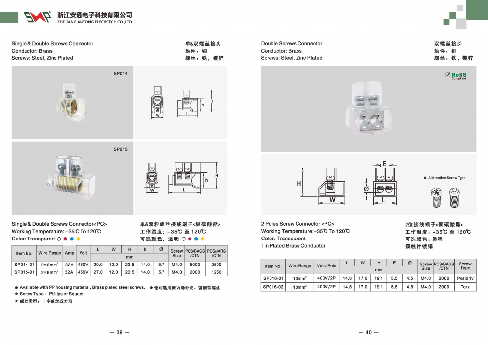
The SP014 and SP015 product page identifies compact screw wire connectors with PC housings, brass contacts and zinc-plated steel screws. The corresponding catalogue reference is PDF page 21, with the SP014/SP015 information on printed page 39 at the left of the spread.
| Catalogue field | SP014-01 | SP015-01 | How to use it |
|---|---|---|---|
| Wire Range | 2 × 6 mm² | 2 × 6 mm² | Preserve the complete configuration when asking about the conductor arrangement |
| Amp | 32 A | 32 A | Read as the listed model rating, with its applicable installation conditions |
| Volt | 450 V | 450 V | Keep it with this model; do not relabel it as an impulse test voltage |
| L | 20.0 mm | 27.0 mm | Compare the length dimension shown in the drawing |
| W | 12.0 mm | 12.0 mm | Check the width against adjacent parts |
| H | 22.5 mm | 22.5 mm | Check the overall height shown in the drawing |
| h | 14.0 mm | 14.0 mm | Use the separate lower-case dimension only where its drawing arrow applies |
| Screw Size | M4.0 | M4.0 | Identify the screw thread size; this is not a tightening torque |
The two rows are different products even though several values match. Ordering “a 32 A, 450 V connector” does not tell purchasing which length, screw arrangement or packaging to obtain. Put the full item number on the bill of materials.
Catalogue reference: Antong catalogue PDF page 21, printed pages 39–40. The left page covers SP014/SP015; the right page covers the separate SP016 series. Use the model row and drawing together.
Open the catalogue page at its original size.
Read conductor capacity without changing its meaning
The notation 2 × 6 mm² contains both a conductor count and a conductor size. Keep both when requesting a connection drawing. It does not mean one 12 mm² conductor, and it does not by itself explain whether the two conductors enter the same opening or separate connection positions.
A compact catalogue row may also omit distinctions between solid conductors, flexible conductors, bare strands and crimped ferrules. Those distinctions matter at the clamp. For a production connection, specify the actual conductor type and termination, then obtain the approved arrangement for that configuration.
For comparison, the SP037 UKK distribution block page separates input and output capacities. Its UKK80A entry lists one input for 6–16 mm², four outputs for 2.5–6 mm² and two outputs for 2.5–16 mm². A wire that fits the input range therefore does not automatically fit every output. Read the column heading as carefully as the number.
Translate the drawing into an installation decision
Use the drawing to establish what L, W, H and h measure. Do not assume that a letter means mounting pitch or insertion depth simply because another supplier uses it that way.
Suppose an assembly has 25 mm available along the connector’s L direction. The catalogue length of SP014-01 is 20 mm, leaving a nominal 5 mm within that envelope. SP015-01 is 27 mm, exceeding it by 2 mm. On length alone, SP014-01 stays on the shortlist and SP015-01 does not.
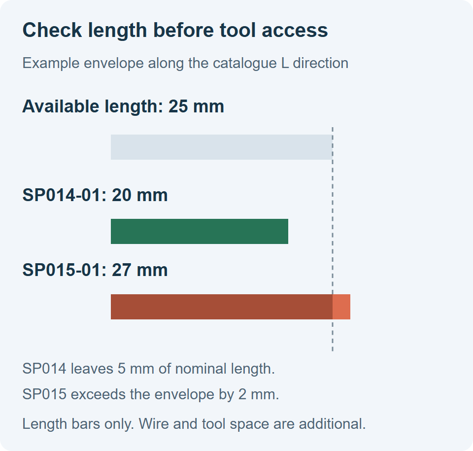
Illustrative envelope comparison based on catalogue lengths. The bars represent length only, not product shape or a mounting drawing.
The remaining 5 mm is not automatically usable wiring space. The next drawing check covers conductor entry, bend space, screwdriver access and clearance to neighbouring parts. A body can fit inside a box while its wires or tool cannot reach the connection.
Check tolerances and mounting details on the current dimensioned drawing before fixing an enclosure design. A catalogue image is useful for selecting a candidate; the drawing for the ordered version controls the assembly.
Keep ratings and installation instructions separate
The SP014/SP015 listing gives 32 A and 450 V. It does not turn the M4.0 screw entry into a torque value, nor does the listed housing temperature range establish full-current operation at every temperature in that range.
Use separate fields for the following decisions:
| Information | Decision it supports | Common reading error |
|---|---|---|
| Current rating and applicable conditions | Whether the connection suits the load | Treating the largest accepted wire as proof of current capacity |
| Voltage rating and applicable approval | Whether the selected version suits the circuit | Mixing operational voltage, insulation voltage and test voltage |
| Specified tightening torque | How the connection must be assembled | Applying a generic M4 bolt torque to the terminal screw |
| Stripping length and termination type | Where the conductor makes contact | Using the visible opening depth as the strip length |
| Housing material and temperature information | Which material version to order | Treating an optional material as interchangeable with the standard version |
| Approval document and exact model coverage | Whether the ordered configuration meets a project requirement | Treating a family-level logo as proof for every variant |
Where the short product table does not supply an installation value, request that value for the exact model. Leave it unresolved in the approval record until it is supplied. A plausible number borrowed from a similar connector creates a false instruction.
Build a purchasing record from the row
For an SP014-01 enquiry, a useful specification would contain these separate entries:
Model: SP014-01, with the required housing material and screw option.
Catalogue reference: the SP014/SP015 table on PDF page 21 and its matching drawing revision.
Application: actual continuous load, circuit voltage and local temperature at the connector.
Conductors: size, construction, insulation diameter, bare or ferruled ends, and the proposed connection arrangement.
Space: available length, width and height, plus conductor and tool access.
Assembly data requested: approved conductor arrangement, stripping length and tightening torque.
Project documents: any required approval covering the exact supplied model and material version.
The catalogue lists alternative material and screw options for this family. Identify the option in the quotation instead of assuming the same row covers every modified configuration.
Questions buyers commonly encounter
Does the screw size tell me the tightening torque
No. M4.0 describes thread size. The permitted assembly torque depends on the terminal’s clamp and housing design and must come from the instruction for that model.
Can I use the highest rating anywhere on the page
Use values from the same model and applicable configuration. For products with several approval tables, keep each set of ratings with its conductor and use conditions rather than combining the largest values.
What should I do when a field is missing
Ask for the specific information that controls the decision. “Please confirm SP014-01 strip length and torque for this conductor and ferrule” is more useful than a general request for additional specifications.
For the next step, compare the SP014/SP015 connector rows with the separately listed input and output arrangements of SP037 UKK distribution blocks. The terminal block selection guide connects this reading process to current, conductor size and installation layout.