
Terminal Block Current Ratings and Derating Explained
A terminal block’s current rating applies to a particular product and set of conditions. Its accepted wire range, housing dimensions or screw diameter cannot independently tell you how much current it may carry. Start with the listed model rating, then check the conductor arrangement, local temperature and installation conditions that support it.
This guide uses Antong catalogue entries to separate three decisions: whether the wire fits, whether the terminal suits the load, and whether the installed assembly needs a lower allowable current.
Keep conductor capacity and current rating as separate fields
Consider these three Antong entries:
| Model | Listed conductor arrangement | Listed current | Listed voltage |
|---|---|---|---|
| SP004-01 | 2.5–4.0 mm² | 3 A | 380 V |
| SP014-01 | 2 × 6 mm² | 32 A | 450 V |
| SP037/UKK80A | Input 1 × 6–16 mm²; outputs in two size groups | 80 A | 690 V |
Sources: SP004 terminal strips, SP014/SP015 connectors, and SP037 UKK distribution blocks. These are catalogue values for the named models, not a comparison test under a common installation condition.
SP004-01 makes the distinction especially clear: its catalogue lists a 2.5–4.0 mm² wire range alongside 3 A. Replacing that current value with a generic figure for a 4 mm² conductor would change the product specification rather than interpret it.
The SP014 entry also needs careful reading. Its 2 × 6 mm² notation is a conductor configuration; it does not mean 64 A, and it does not permit combining two 32 A current allowances. The model row lists 32 A.
Understand what a thermal rating describes
Current produces heat in the conductive path. The resulting temperature depends on electrical resistance and the path available for that heat to leave the connection. The wire, surrounding air, adjacent loaded parts and enclosure all contribute to the installed condition.
Temperature rise is the difference between the measured temperature at the specified point and the relevant ambient reference. If that ambient reference rises, the same temperature rise produces a higher component temperature. This is why a room-temperature rating cannot be applied to a hot enclosure without checking the applicable conditions.
Phoenix Contact’s electrical testing guide describes different IEC and UL temperature-rise test arrangements and limits. The comparison shows why ratings from different systems must retain their own test and use conditions. It does not establish which approvals any particular Antong model holds.
For selection, keep the current rating with the exact model, conductor, termination and applicable approval information. A line showing only an ampere value is a starting point for that check, not the complete application specification.
Apply derating only with the relevant conditions
A derating curve can describe how allowable current changes with ambient temperature for a defined connection arrangement. Read its axes, conductor size and number of loaded positions before using it. A curve for a different connector or a different population of contacts may not describe the assembly being selected.
PTR HARTMANN’s current-carrying capacity guidance describes connector curves tied to wire size, pole count and ambient temperature. Its stated reduction factor belongs to the curve-development method. It is not a universal instruction to multiply every manufacturer’s catalogue current by 0.8.
Use the following distinctions when checking an application:
| Change in the application | Information needed to assess it |
|---|---|
| Higher temperature near the terminal | Permitted current at that local ambient temperature for the selected configuration |
| More adjacent positions loaded | The rated or tested population of loaded contacts |
| Different conductor size or end preparation | The connection and thermal conditions covering that conductor arrangement |
| A smaller enclosure or a nearby heat source | The expected temperature around the terminal in the completed equipment |
| A different housing material or product option | Ratings and installation conditions for that exact version |
If the available product sheet does not provide the required curve or application limit, request the condition-specific information. Do not invent a percentage reduction. Selecting a higher catalogue-current model may create a useful candidate, but it does not resolve an unknown temperature limit by itself.
The upper temperature shown for a housing or product also should not be read as permission to operate at full listed current at that temperature. Electrical loading and the temperature rating must be interpreted together.
Check the shared input of a distribution block
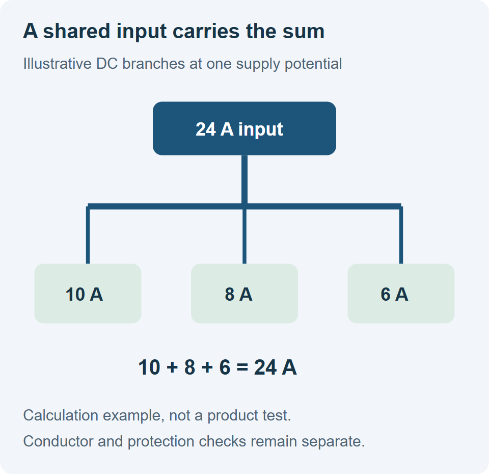
For a simple DC distribution example, suppose three branches draw 10 A, 8 A and 6 A simultaneously from the same supply potential. Their shared input carries 10 + 8 + 6 = 24 A. The input path must be assessed for the total load; each branch conductor must be assessed for its own duty and protection.
Calculation example only. It is not an Antong test result, a wiring diagram for a specific block or a cable-sizing recommendation.
The SP037/UKK80A catalogue entry lists 80 A with one input and six outputs. It does not mean that each output can draw 80 A simultaneously. For the 24 A example, the listed block current is above the calculated shared load, but that comparison alone does not approve the circuit. The input conductor, individual output ranges, branch protection and installed thermal conditions still have to match their applicable limits.
Do not add the maximum sizes of all output openings and treat the result as either the required input size or a new block current rating. Connection counts describe geometry; the load calculation describes current flow.
Build a condition-specific enquiry
A current-rating enquiry should describe the job the connection will do. For a distribution block, include:
- The exact model and housing or connection options.
- The supply type and voltage, continuous input load, and simultaneously operating branch loads.
- Input and output conductor sizes, construction and end preparation.
- The expected local temperature and nearby sources of heat.
- The installation arrangement, enclosure and number of adjacent loaded parts.
- The destination-market requirements and documents needed for the ordered configuration.
Ask for the permitted load under those conditions and the applicable assembly instructions. Keep the returned information with the drawing and bill of materials so that a later change of wire, enclosure or product option triggers a deliberate review.
Questions buyers commonly encounter
Can I calculate terminal current from wire size
Wire size is one input to selection. The completed terminal has its own conductive path, clamp, insulation and rating conditions. Use its declared current rather than replacing it with a general wire-current table.
Can I increase current by tightening the screw more
Use the specified torque. Additional tightening is not a method of uprating the terminal and can damage the connection.
Does a lower operating current guarantee that the terminal will remain cool
A lower load generally reduces resistive heating when other conditions stay the same. A loose connection, incorrect termination or unsuitable ambient temperature can still produce a problem. Compare the actual assembly with the model’s installation and thermal limits.
For an initial shortlist, review the separate conductor and current columns in SP014/SP015 connectors and SP037 UKK distribution blocks. Then describe the application conditions that the selected model must satisfy.